Piston ring for a piston compressor, and piston compressor

a piston compressor and piston ring technology, which is applied in the direction of machines/engines, liquid fuel engines, positive displacement liquid engines, etc., can solve the problems of increasing the requirement to compress fluids to even higher final pressures, rapid wear of the piston ring, and the suitability of the known piston ring for compressors, etc., to achieve improved mechanical and/or tribological properties, low tensile strength, and reliable operation

Active Publication Date: 2020-03-26
BURCKHARDT COMPRESSION AG
View PDF0 Cites 6 Cited by
  • Summary
  • Abstract
  • Description
  • Claims
  • Application Information

AI Technical Summary

Benefits of technology

[0019]A plastic very well-suited for the sealing ring is polytetrafluoroethylene (PTFE), to which fillers, which are preferably still generally inorganic, such as carbon, graphite, glass fibers etc., are added to improve its physical, mechanical and / or tribological properties, in particular to impart dry-running properties. Despite these fillers, the use of previously known sealing rings made from PTFE was limited to low pressure differences owing to the pronounced tendency for cold flow of PTFE. The piston ring according to the invention has the advantage that a sealing ring composed of PTFE can be operated reliably even with relatively high pressure differences. This may be explained with reference to the following example of a dry-running “Piston ring 1”. The illustrative piston ring 1 comprises a sealing ring composed of filled PTFE, wherein the PTFE is filled with carbon or graphite. At a temperature of 20° C., a sealing ring of this kind has a tensile strength of 10 MPa. The base ring and the top ring are composed of filled PEEK. At a temperature of 250° C., a base ring and a top ring of this kind have a tensile strength of 18 MPa. In this illustrative embodiment, the piston ring according to the invention can be operated in dry-running mode without problems at 250° C. although the sealing ring has an extremely low tensile strength at this temperature since the sealing ring is held in the axial direction between the support rings, i.e. between the base ring and the top ring, and it is not possible for the sealing ring to escape in the radial direction since it rests against the inner wall of the cylinder in the radial direction. The distance between the base ring and the top ring and the inner wall of the cylinder is preferably a few tenths to a few hundredths of a millimeter.

Problems solved by technology

However, there is an increasing requirement to compress fluids to even higher final pressures.
However, the known piston ring has only limited suitability for use with high pressure differences since it exhibits pronounced cold flow under load, resulting in rapid wear of the piston ring.
The known piston ring thus has only limited suitability for compressors with a high final pressure of over 200 bar.

Method used


Image

  • Piston ring for a piston compressor, and piston compressor
  • Piston ring for a piston compressor, and piston compressor
  • Piston ring for a piston compressor, and piston compressor

Examples


Embodiment Construction

[0003]It is the object of the invention to design a piston ring and a piston compressor which have more advantageous operating characteristics.

[0004]This object is achieved by a piston ring having the features of claim 1. Dependent claims 2 to 8 relate to further advantageous embodiments of the invention. The object is furthermore achieved by a piston compressor having the features of claim 9. Dependent claims 10 to 12 relate to further advantageous embodiments. The object is furthermore achieved by using the piston ring according to the invention in a piston compressor to compress a fluid to a pressure of more than 500 bar.

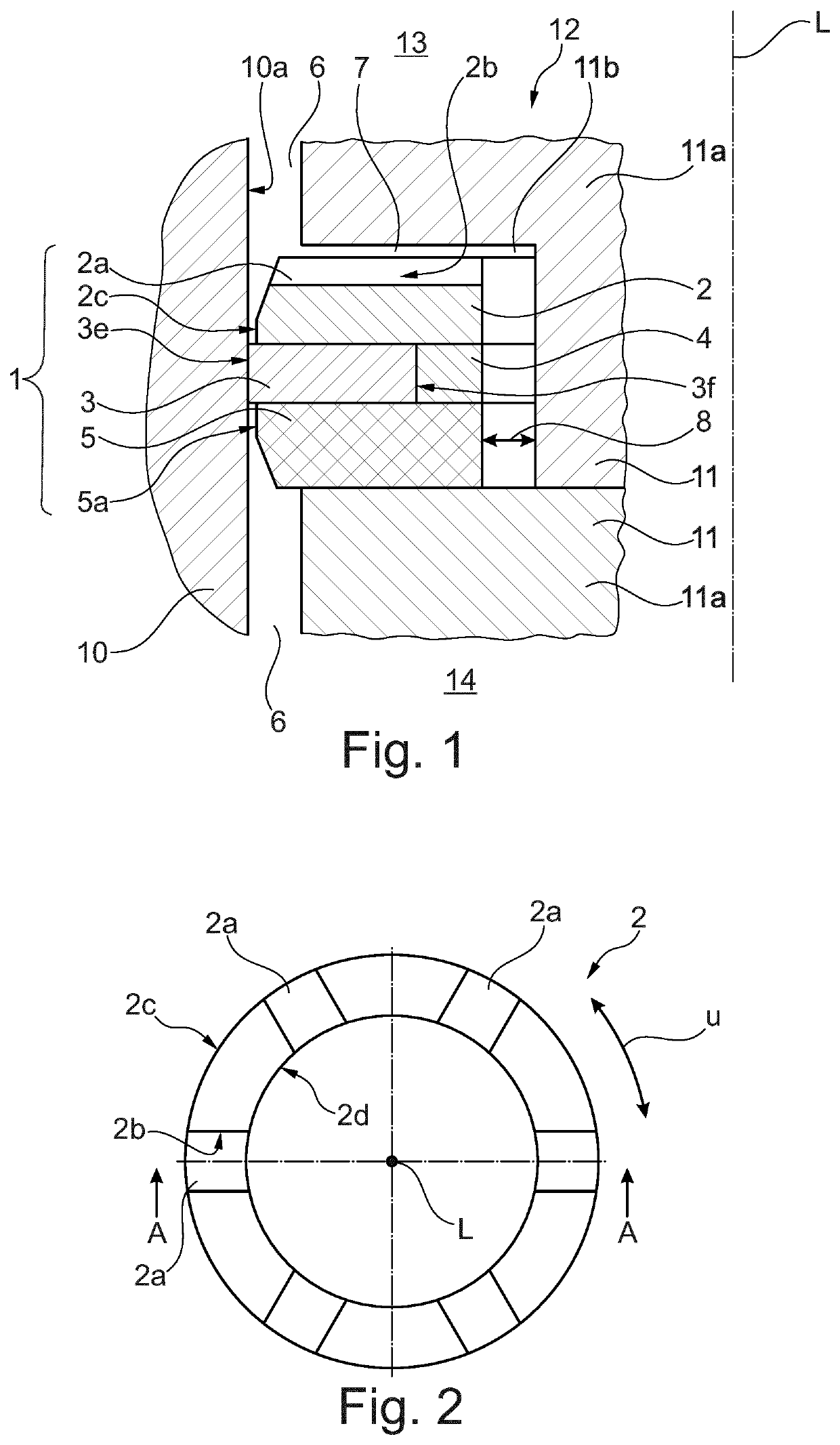
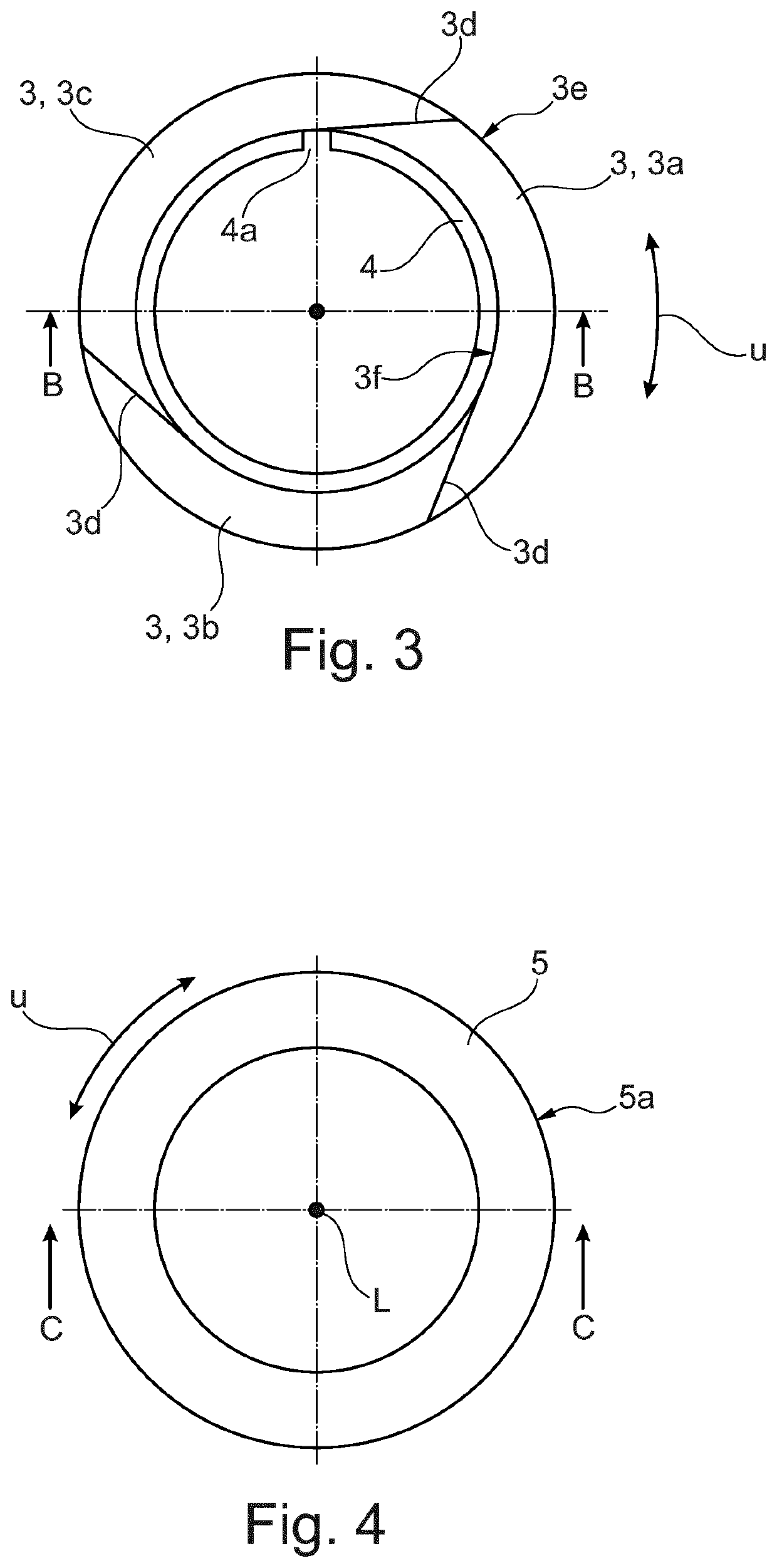
[0005]In particular, the object is achieved by means of a piston ring comprising an endless base ring and a sealing ring, wherein the base ring has a radially outwardly directed base ring face, and wherein the sealing ring has a radially outwardly directed sealing face and a radially inwardly directed, circular sealing ring inner side, wherein the sealing ring ha...


PUM


Abstract

Piston ring having an endless base ring and sealing ring have a radially outwardly directed base ring face side. The sealing ring has a radially inwardly directed, circularly running sealing ring inner side with three tangential cuts separating three sealing ring segments are arranged in a circumferential direction (U). The base and sealing rings are arranged in succession in a longitudinal direction (L). A top ring is arranged to adjoin the sealing ring having a top ring has a radially outwardly directed top ring outer side and a radially inwardly directed top ring inner side. The top ring has, on the side opposite the sealing ring, a radially running return flow channel extending radially, the sealing face side protrudes in a radial direction beyond the top ring outer side and the base ring face side. The base and the top rings have a greater tensile strength than the sealing ring.

Description

[0001]The invention relates to a piston ring for a piston compressor in accordance with the preamble of claim 1. The invention furthermore relates to a piston compressor.PRIOR ART[0002]Piston compressors comprising a cylinder and a piston that can be moved linearly therein are known. In one possible embodiment, a piston ring is arranged on the piston, wherein the piston ring slides along the cylinder wall, ensuring that the piston ring seals off the compression chamber delimited by the cylinder and the moving piston. Document WO 98 / 55783A1 discloses a dry-running piston compressor having a piston ring which is arranged on the piston and rubs against the cylinder wall. This dry-running piston compressor is well-suited to the compression of hydrogen to a final pressure of up to 200 bar, for example. However, there is an increasing requirement to compress fluids to even higher final pressures. However, the known piston ring has only limited suitability for use with high pressure differ...

Claims


Application Information

Patent Timeline
Patent Type & Authority Applications(United States)
IPC IPC(8): F16J9/26F16J15/28F16J15/00
CPCF16J15/006F16J9/26F16J15/28F04B53/143F16J9/08F16J15/24F04B15/08
Inventor FEISTEL, NORBERT
Owner BURCKHARDT COMPRESSION AG
Why Eureka
Try Eureka