Eureka AIR delivers breakthrough ideas for toughest innovation challenges, trusted by R&D personnel around the world.

Methods for fabricating silicon MEMS gyroscopes with upper and lower sense plates

Active Publication Date: 2020-03-26
CHARLES STARK DRAPER LABORATORY
View PDF0 Cites 2 Cited by
  • Summary
  • Abstract
  • Description
  • Claims
  • Application Information

AI Technical Summary

Benefits of technology

The patent text discusses the use of a glass process to make devices, which can have lower parasitic capacitances than silicon wafers. However, the glass process has several drawbacks, including differences in thermal expansion and the need for costly packaging. The text proposes a solution using a no-glass process that eliminates the need for expensive vacuum packaging. The technical effect of this patent is to provide a cost-effective and reliable method for making devices with lower parasitic capacitances and better performance.

Problems solved by technology

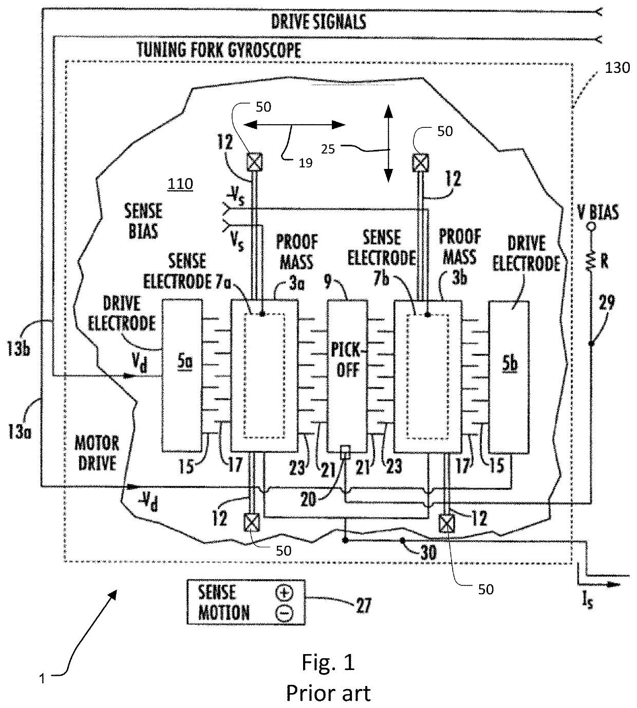
Another issue concerns parasitic capacitance.
One of the main drawbacks of the glass process is that it includes several different materials, and, in particular, relatively large pieces of glass.
Differential thermal expansion of the glass and silicon is a leading cause of errors in the fabricated gyroscopes, as drive and sense frequencies shift relative to each other with the changing stresses.
Additionally, the anodic bond cannot form a vacuum tight seal without shorting the signal traces together, so the device must be packaged into a vacuum-sealed package.

Method used


Image

  • Methods for fabricating silicon MEMS gyroscopes with upper and lower sense plates
  • Methods for fabricating silicon MEMS gyroscopes with upper and lower sense plates
  • Methods for fabricating silicon MEMS gyroscopes with upper and lower sense plates

Examples


Embodiment Construction

[0024]The invention now will be described more fully hereinafter with reference to the accompanying drawings, in which illustrative embodiments of the invention are shown. This invention may, however, be embodied in many different forms and should not be construed as limited to the embodiments set forth herein; rather, these embodiments are provided so that this disclosure will be thorough and complete, and will fully convey the scope of the invention to those skilled in the art.

[0025]As used herein, the term “and / or” includes any and all combinations of one or more of the associated listed items. Further, the singular forms and the articles “a”, “an” and “the” are intended to include the plural forms as well, unless expressly stated otherwise. It will be further understood that the terms: includes, comprises, including and / or comprising, when used in this specification, specify the presence of stated features, integers, steps, operations, elements, and / or components, but do not pre...


PUM

PropertyMeasurementUnit
Massaaaaaaaaaa
Electrical conductoraaaaaaaaaa

Abstract

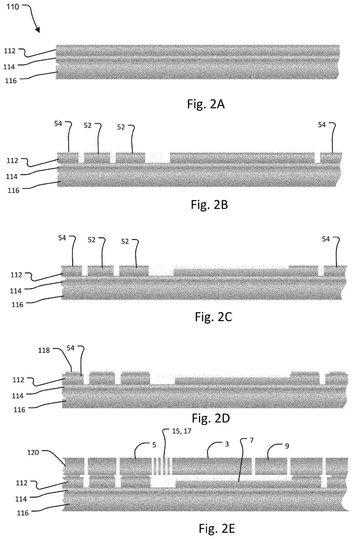
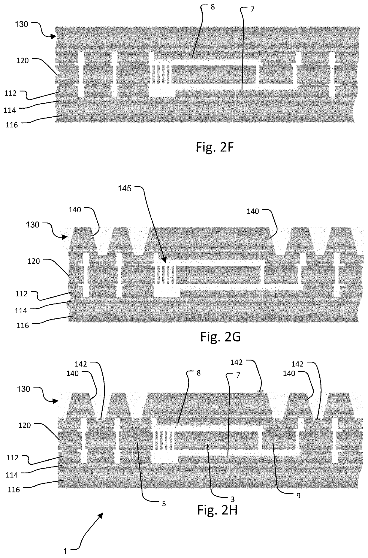
Methods for fabricating MEMS tuning fork gyroscope sensor system using silicon wafers. This provides the possibly to avoid glass. The sense plates can be formed in a device layer of a silicon on insulator (SOI) wafer or in a deposited polysilicon layer in a few examples.

Description

RELATED APPLICATIONS[0001]This application claims the benefit under 35 USC 119(e) of U.S. Provisional Application No. 62 / 735,512, filed on Sep. 24, 2018, which is incorporated herein by reference in its entirety.BACKGROUND OF THE INVENTION[0002]Currently vehicle localization is performed by fusing data from a combination of sensors that may include inertial measurement units (IMUs), wheel speed sensors, global positioning system (GPS) chipsets, and perception sensors that observe the environment external to the vehicle, including RADAR systems, cameras, and LIDAR systems. Of these sensors, the IMU, is the least susceptible to the external environment, making it a more reliable source of localization information.[0003]Further, analysis has shown that the most critical component for localization accuracy within an IMU is the gyroscope. A good candidate for the IMU gyroscope is type of gyroscope called a tuning fork gyroscope. These devices can be fabricated using MicroElectroMechanica...

Claims


Application Information

Patent Timeline
IPC IPC(8): G01C19/5621B81C1/00B81B3/00G01C19/5628
CPCB81B2207/096B81C2203/035B81B3/0097G01C19/5621B81C1/00166B81B2201/0242B81B2203/04B81C2201/0133B81C2201/0132B81C2203/036G01C19/5628B81B7/0038B81C2203/0118G01C19/5769G01C19/5747
Inventor COOK, EUGENE H.BERNSTEIN, JONATHAN J.BANCU, MIRELA G.WEINBERG, MARC STEVENSAWYER, WILLIAM
Owner CHARLES STARK DRAPER LABORATORY
Why Eureka
Eureka Blog
Learn More