
Cell observation device

Active Publication Date: 2020-03-26
SHIMADZU CORP
View PDF0 Cites 1 Cited by
  • Summary
  • Abstract
  • Description
  • Claims
  • Application Information

AI Technical Summary

Benefits of technology

The present invention is a device that allows a user to observe cells while measuring them in real-time using a hologram image. This device helps to detect any problems or improper handling during the measurement, without having to wait for other images to be displayed. This way, the user can quickly discontinue the measurement and avoid wasting time. Overall, this device improves the efficiency of cell observation.

Problems solved by technology

In general, cells are transparent and difficult to observe with a normal optical microscope.
A problem with the phase-contrast microscope is that it requires the focusing operation before recording the microscopic image, so that a significant amount of time is required for the measurement when it is necessary to take a microscopic image for each of the small areas defined by dividing a large observation target area.
Therefore, it is unnecessary to perform the focusing for every shot of image.
Such a computation is considerably complex and requires a significant amount of calculation.
Performing such a computation for a large number of small areas means that the amount of computation will be enormous.
Therefore, even a computer with a high level of power requires a certain length of time from the beginning of the measurement to the completion of the reproduction of the phase image for the observation target area.
A measurement will be completely useless if there is a problem with the cell culture plate being observed, such as the presence of a foreign object in the plate, or if the measurement is unsuccessful or improperly conducted.
This means that the measurement results in a waste of time and lowers the efficiency of the tasks of observing and analyzing the cells.

Method used


Image

  • Cell observation device
  • Cell observation device
  • Cell observation device

Examples


Embodiment Construction

[0051]One embodiment of the cell observation device according to the present invention is hereinafter described with reference to the attached drawings.

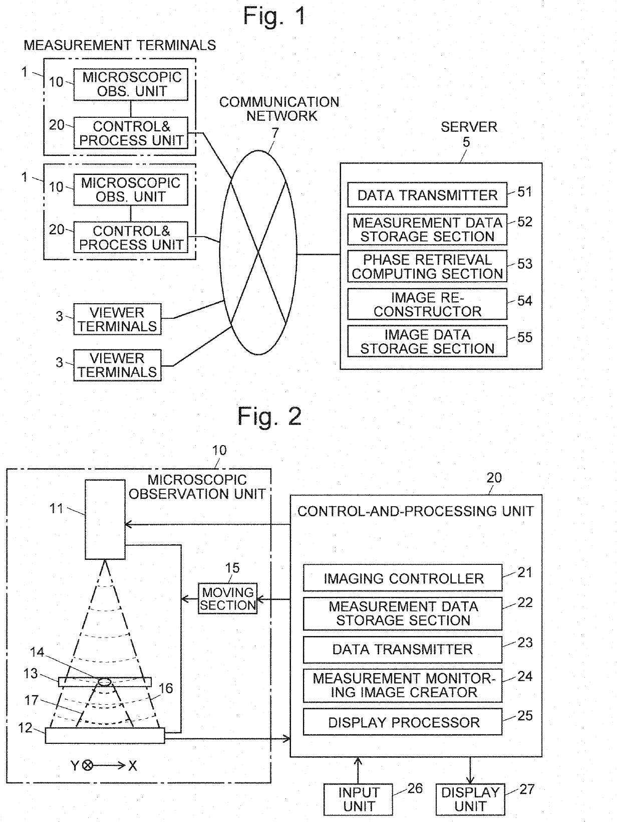
[0052]FIG. 1 is an overall configuration diagram of the cell observation device according to the present embodiment. FIG. 2 is a schematic configuration diagram of a measurement terminal in the cell observation device according to the present embodiment.

[0053]The cell observation device according to the present embodiment includes measurement terminals 1, viewer terminals 3 and a server 5, which are connected to each other via a communication network 7, such as the Internet or intranet. FIG. 1 shows two measurement terminals 1 and two viewer terminals 3. Each of the two types of terminals may be provided in any appropriate number.

[0054]The server 5 is a high-performance computer and has functional blocks realized by dedicated software installed on the same computer, including a data transmitter 51, measurement data storage section 52...


PUM


Abstract

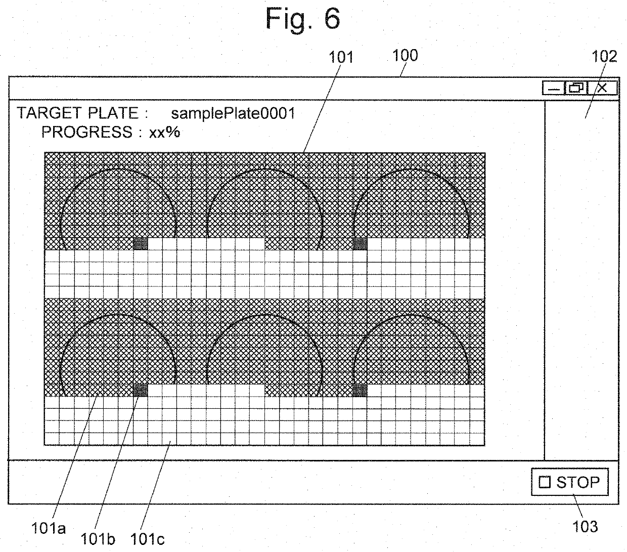
In a microscopic observation unit (10), hologram data is acquired at each measurement position on a cell culture plate (13) while a light-source section (11) and other elated sections are gradually moved by a moving section (15). Every time a set of data for one measurement position is acquired, a measurement monitoring image creator (4) creates a thumbnail age by reducing the size of a hologram image which is based on original data (two-dimensional distribution of light intensity). A display processor (25) pastes the create thumbnail image to progressively complete the hologram image of the entire plate to be displayed on a display unit (27). A measurement operator watches the hologram image during the execution of the measurement. When it has been concluded that the ongoing measurement is inappropriate, the operator presses a measurement stop button to immediately discontinue the measurement. Thus, When there is a problem with the measurement, such as a foreign object mixed in the sample, the measurement can be discontinued before a phase image or intensity image based on the hologram data is reconstructed on the server after the completion of the entire measurement, so as to avoid wasting time for the useless measurement.

Description

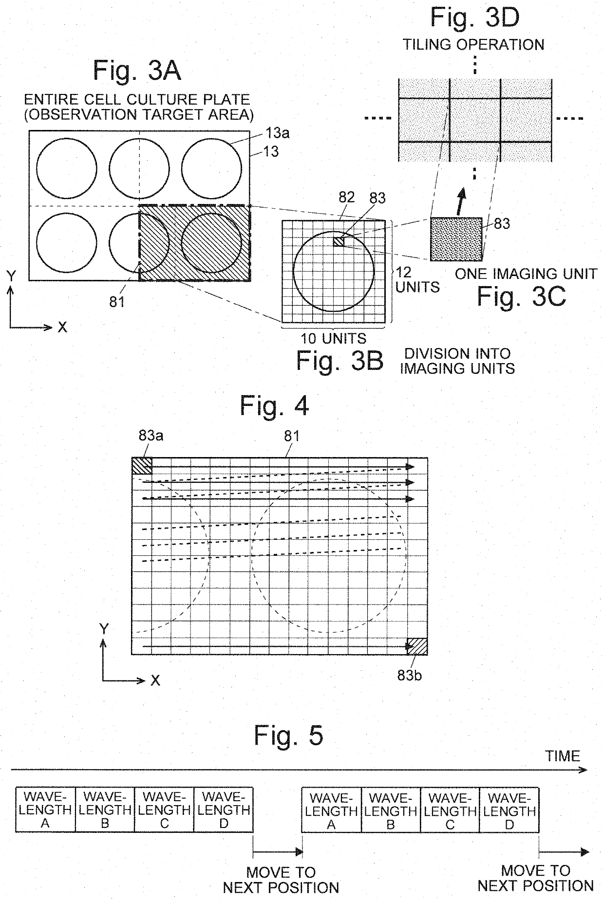
TECHNICAL FIELD[0001]The present invention relates to a cell observation device for observing the state of a cell, and more specifically, to a cell observation device configured to obtain a hologram which records an interference pattern formed by object wave and reference wave by means of a holographic microscope, and to create a phase image, intensity image or other types of images after computing phase information or intensity information based on the hologram data.BACKGROUND ART[0002]In recent years, studies which use pluripotent stem cells, such as induced pluripotent stem cells (iPS cells) or embryonic stem cells (ES cells), have been popularly conducted in the area of regenerative medicine. In general, cells are transparent and difficult to observe with a normal optical microscope. Accordingly, phase-contrast microscopes have been commonly used for the observation of the cells. A problem with the phase-contrast microscope is that it requires the focusing operation before recor...

Claims


Application Information

Patent Timeline
IPC IPC(8): G03H1/00G03H1/04G03H1/22G01N21/45
CPCG03H2001/005G03H1/0005G03H1/22G03H1/0443G01N21/453G03H2001/0452C12M1/34G02B21/00G03H2227/03G03H2001/0447G03H2001/2655G03H2001/266G03H1/0866G01N2015/1006G01N2015/1454G01N15/1468
Inventor YAMAKAWA, MOMOYOYAMAMOTO, SHUHEI
Owner SHIMADZU CORP
Learn More