Eureka AIR delivers breakthrough ideas for toughest innovation challenges, trusted by R&D personnel around the world.

Calibration device and method for determining an optimal operating frequency of a power transfer system

Active Publication Date: 2020-03-26
GENERAL ELECTRIC CO
View PDF9 Cites 2 Cited by
  • Summary
  • Abstract
  • Description
  • Claims
  • Application Information

AI Technical Summary

Benefits of technology

The patent describes a calibration device for a wireless power transfer system that can determine the best frequency for optimal performance. The device includes a controller that sends different input voltage signals to the system's power exchange coil, and a voltage sensor that measures the output voltage signals across the system's electrical load. By analyzing these signals, the controller can determine the optimal frequency for the system. This helps to minimize voltage variations and ensure consistent performance. The calibration device can be easily integrated into existing wireless power transfer systems, making it easy to optimize their performance.

Problems solved by technology

However, due to environmental impact, such connectors and wires may be damaged or corroded.
Hence, establishing a physical connection between the power source and the batteries in the vehicle may involve cumbersome safety measures.
Also, this type of contact-based power transfer system tends to be bulkier and heavier compared to the contactless power transfer system.
Consequently, a voltage gain of the power transfer system may vary drastically.
Such a sudden increase in the output voltage and / or drastic variations in the voltage gain may lead to failure of operation of the power transfer system and / or result in damage to one or more components in the power transfer system.

Method used


Image

  • Calibration device and method for determining an optimal operating frequency of a power transfer system
  • Calibration device and method for determining an optimal operating frequency of a power transfer system
  • Calibration device and method for determining an optimal operating frequency of a power transfer system

Examples


Embodiment Construction

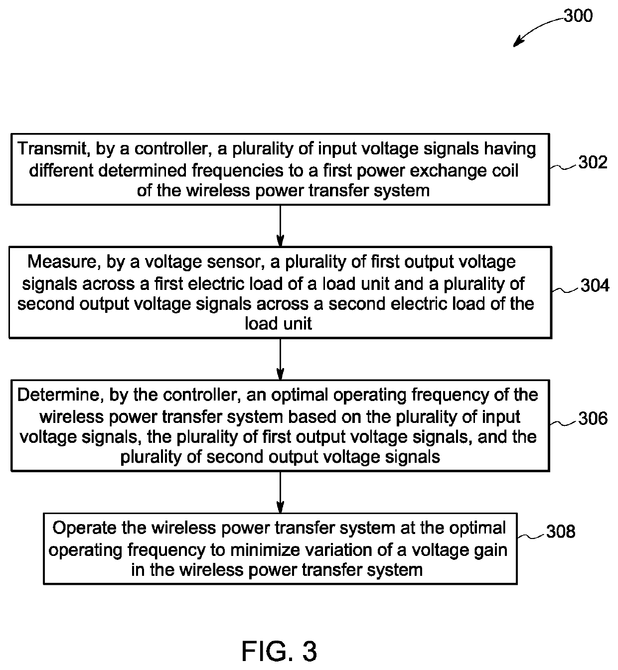
[0012]As will be described in detail hereinafter, various embodiments of a system and method for determining an optimal operating frequency of a wireless power transfer system are disclosed. In particular, a calibration device that is configured to determine the optimal operating frequency of the wireless power transfer system is presented. By operating the wireless power transfer system at this optimal operating frequency, an output voltage of the wireless power transfer system is controlled or maintained within a desired threshold value independent of variations in a device load coupled to the wireless power transfer system and / or impedance in the wireless power transfer system.

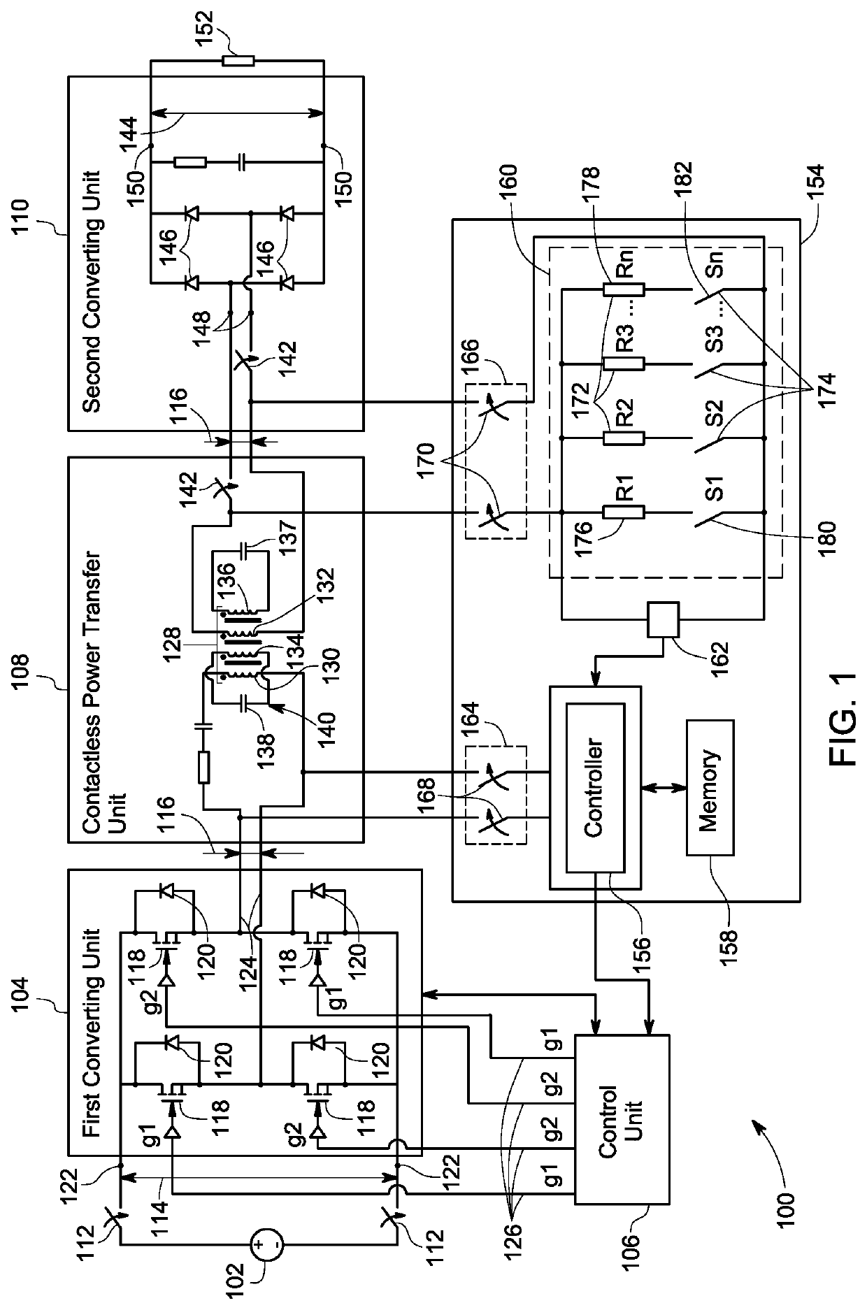
[0013]FIG. 1 is a diagrammatical representation of a wireless power transfer system 100, in accordance with aspects of the present specification. The wireless power transfer system 100 is used to transmit electrical power from a power source 102 to one or more device loads 152 such as batteries, mobile devi...


PUM


Abstract

A calibration device includes a controller configured to communicate a plurality of input voltage signals having different determined frequencies to a first power exchange coil. Also, the calibration device includes a load unit coupled to a second power exchange coil, where the load unit includes at least a first electrical load and a second electrical load. Further, the calibration device includes a voltage sensor configured to measure a plurality of first output voltage signals across the first electrical load and a plurality of second output voltage signals across the second electrical load, and where the controller is configured to determine an optimal operating frequency of a wireless power transfer system based on the plurality of input voltage signals, the plurality of first output voltage signals, and the plurality of second output voltage signals.

Description

BACKGROUND[0001]Embodiments of the present specification relate generally to wireless power transfer systems, and more particularly to a calibration device and method for determining an optimal operating frequency of a wireless power transfer system.[0002]In general, power transfer systems are widely used to transfer power from a power source to one or more electrical loads, such as batteries in a hybrid or electric vehicle. Typically, the power transfer systems include contact-based power transfer systems or contactless power transfer systems. In the contact based power transfer systems, components such as plugs, socket connectors, and wires are physically coupled to the batteries for charging the batteries. However, due to environmental impact, such connectors and wires may be damaged or corroded. Also, high values of currents and voltages are used for charging the batteries. Hence, establishing a physical connection between the power source and the batteries in the vehicle may in...

Claims


Application Information

Patent Timeline
IPC IPC(8): H02J50/12H02J7/02H02J5/00H02J50/90
CPCH02J50/12H02J5/005H02J50/90H02J7/025Y02T90/16Y02T10/7072Y02T90/14B60L53/126B60L53/122H02J50/40Y02T10/70
Inventor KANAKASABAI, VISWANATHANRAGHUNATHAN, ARUN KUMARBHOGINENI, SATISHBABU
Owner GENERAL ELECTRIC CO
Why Eureka
Eureka Blog
Learn More