Phototherapy device

a phototherapy device and portable technology, applied in the field of light therapy devices, can solve the problems of not allowing everyone to be dominators, unportable devices, and difficult to be operated by any one user, and achieve the effect of facilitating this novel phototherapy devi

Inactive Publication Date: 2020-04-02
GCSOL TECH
View PDF0 Cites 4 Cited by
  • Summary
  • Abstract
  • Description
  • Claims
  • Application Information

AI Technical Summary

Benefits of technology

[0008]The primary objective of the present invention is to disclose a phototherapy device that can be operated by press activation, touch control, or remote control, so as to emit a specific light to illuminate human skin. The phototherapy device mainly comprises a phototherapeutic host and a patch module, wherein the phototherapeutic host is particularly designed to have a modular structure, so as to be manufactured and / or sold individually. On the other hand, the patch module is designed to have a patch sheet (or wearing body) with a connection base, such that the phototherapeutic host can be attached to and detached from the patch sheet. By such design, it is facilitated this novel phototherapy device being patched on different parts of a user by combining the phototherapeutic host with the patch sheet (or wearing body) having correspondingly-suitable appearance or structure, thereby making the user to feel a comfortable sense of wearing the phototherapy device.

Problems solved by technology

Because there is danger lurking in the progress of the acupuncture treatment, government does not permit everyone to be a dominator of the acupuncture treatment except for a relative medical specialist who has a professional license.
On the other hand, it is known that the acupuncture treatment may cause patient suffer from certain side effect(s) or undesired accidents, like fainting during acupuncture treatment and wound infection.
However, owing to the fact that both the conventional light therapy apparatus and the conventional magnetic force generator have a large and complex structure, each of the two apparatuses is unportable and is not easy to be operated by any one user.
The commercial van-type light therapy apparatus is commonly assembled in a specific site and cannot be moved arbitrarily due to its large apparatus volume.
Although there is one kind of light therapy device having smaller volume developed for replacing the van-type light therapy apparatus, the operation ways of the small-volume light therapy device are still complicated.
Strictly speaking, the light therapy device just has a limited volume miniaturization and still has a certain thickness, causing the light therapy device cannot be portable yet.
However, owing to the fact that a number of patch units of the phototherapeutic device only have a limited unit lifetime and are unable to be replaced, causing the phototherapeutic device also has a limited device lifetime.
In despite of adding the number of the patch units is found to prolong the unit lifetime, that would simultaneously leads a whole thickness of the phototherapeutic device to be increased, thereby causing the user to feel a uncomfortable sense of wearing the phototherapeutic device.
However, as mentioned above, the patch units of the phototherapeutic device are non-replaceable.
Therefore, above descriptions have revealed that, how to improve or redesign the structure of the conventional phototherapeutic device has become an important issue.

Method used


Image

  • Phototherapy device
  • Phototherapy device
  • Phototherapy device

Examples


first embodiment

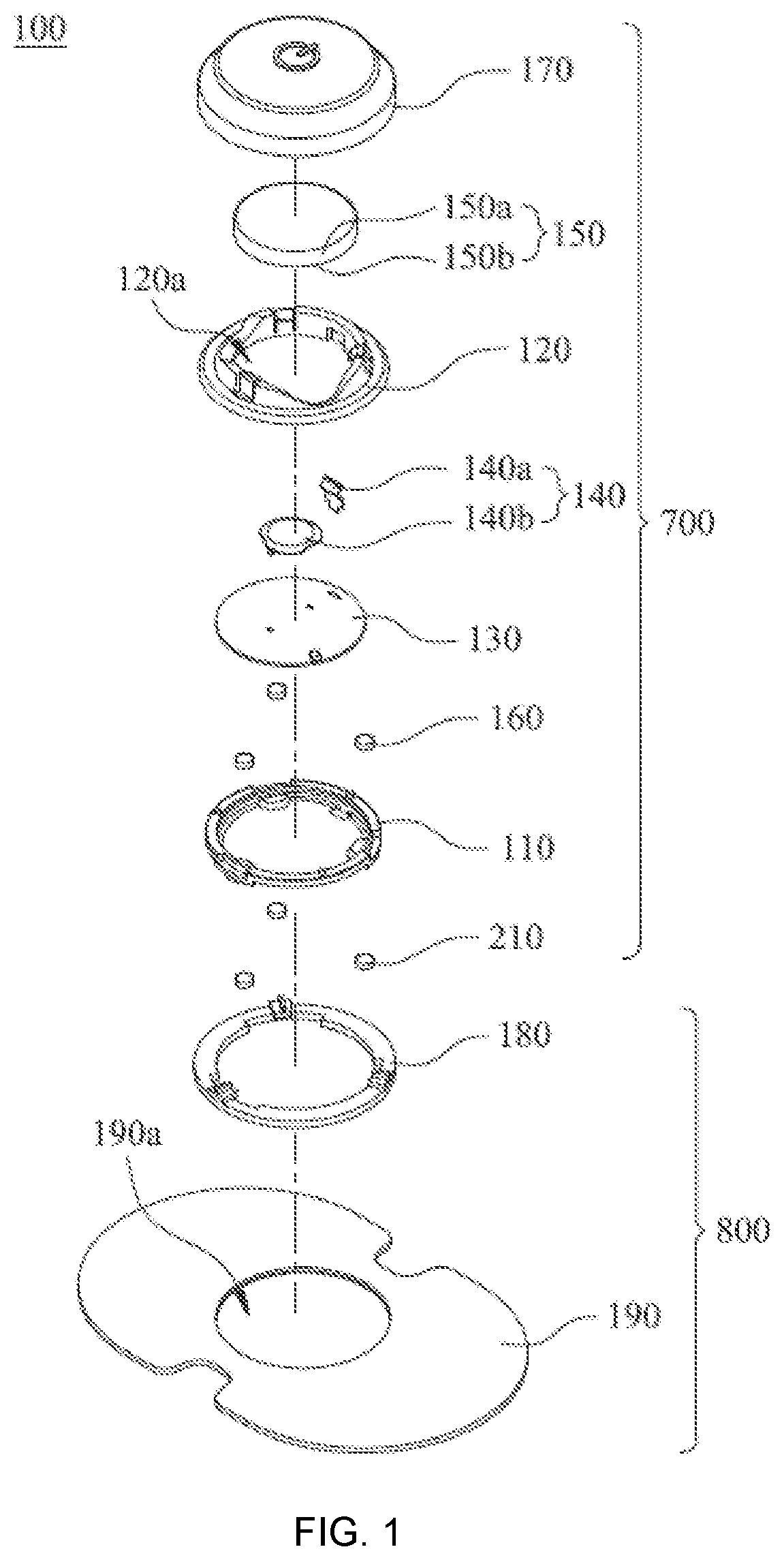
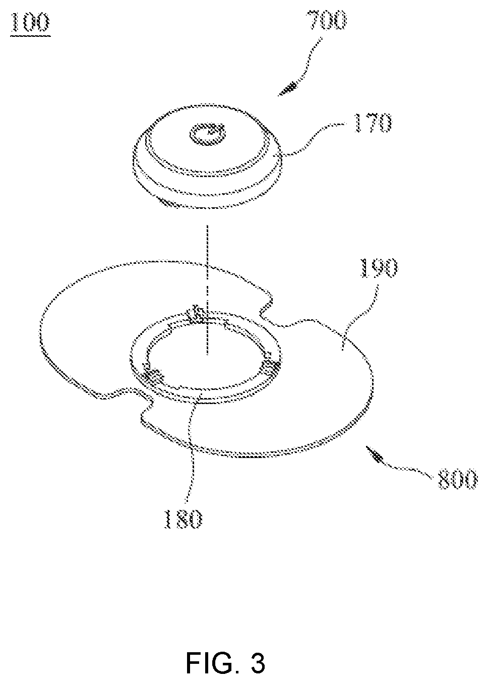
[0043]With reference to FIG. 1, there is provided an exploded diagram of a phototherapy device according to the present invention. As FIG. 1 shows, the phototherapy device 100 consists of a phototherapeutic host 700 and a patch module 800, wherein the phototherapeutic host 700 can be attached to and detached from the patch module 800. In the present invention, the phototherapeutic host is particularly designed to have a modular structure comprising a base 110, a fixing means 120, a PCB 130, a plurality of electrically-conductive members 140, a lighting unit 160, a power unit 150, and a cover 170, such that the phototherapeutic host 700 can be manufactured and / or used individually. On the other hand, the patch module 800 comprising a patch sheet 190 and a connection base 180.

[0044]As described in detail below, the fixing means 120 is connected to the base 110, and both the fixing means 120 and the base 110 have a hollow structure. Moreover, the PCB 130, comprising a driving circuit t...

second embodiment

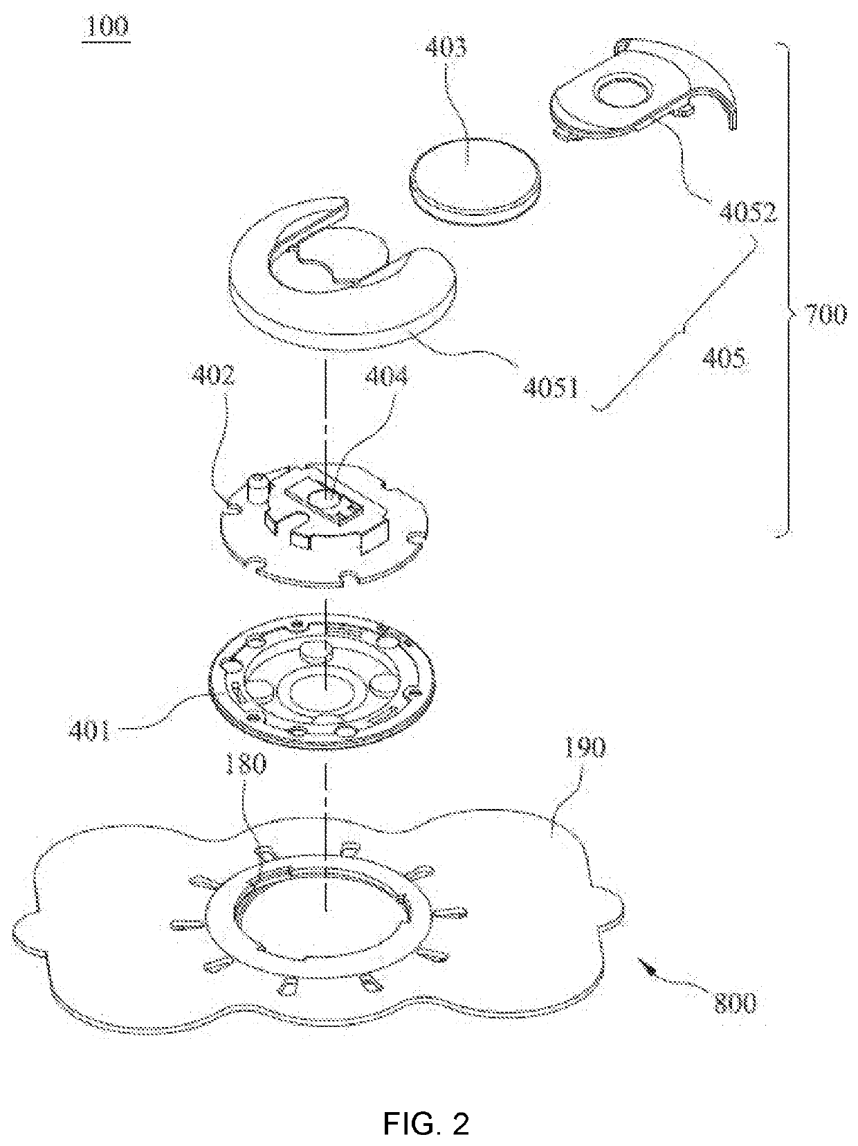
[0052]FIG. 2 shows an exploded diagram of the phototherapy device according to the present invention. According to the particular design of the present invention, the phototherapeutic host 700 having modular structure can be manufactured, sold and / or used individually. In other words, each of the base 401, the PCB 402, the power unit 403, a touch switch 404, and a cover 405 is replaceable, so as to make the phototherapeutic host 700 possess different functions.

[0053]As FIG. 2 shows, the PCB 402 is connected to the base 401, and comprises driving circuit and electrically-conductive members for electrically connecting the power unit 403. On the other hand, the touch switch 401 is disposed between the PCB 402 and the base 401, and is electrically connected to the driving circuit. Moreover, the cover 405 is used for covering the PCB 402, the power unit 403, the lighting unit, and the touch switch 404. In FIG. 2, the lighting unit is not shown because it is disposed onto the bottom surfa...


PUM

PropertyMeasurementUnit
electrically-conductiveaaaaaaaaaa
transparentaaaaaaaaaa
magneticaaaaaaaaaa

Abstract

Disclosures of the present invention describe a phototherapy device mainly comprises a phototherapeutic host and a patch module having a connection base, wherein the patch module can be assembled with the phototherapeutic host by letting the connection base be connected with the base through an interlocking mechanism, a rotary locking mechanism or a magnetic lock mechanism. In addition, the phototherapeutic host can be attached to and detached from the patch module. Briefly speaking, this phototherapy device has advantages of simple structure, small volume, being portable, being easy to be operated, and having patch units that are replaceable. In addition, the phototherapeutic host is designed to have a modular structure comprising a base, a PCB, a lighting unit, and a cover, such that the phototherapeutic host can be manufactured and/or used individually.

Description

BACKGROUND OF THE INVENTION1. Field of the Invention[0001]The present invention relates to the technology field of light therapy devices, and more particularly to a portable phototherapy device that has small volume and is easy to be operated. This phototherapy device can be patches on a user's skin so as to emit a light with at least one wavelength to target acupuncture point of the user, thereby achieving a light therapy in combination with a magnetic field therapy or a vibration excitation on the acupuncture point.2. Description of the Prior Art[0002]Acupuncture treatment is one kind of traditional Chinese pain relieving therapy. During a patient receiving the acupuncture treatment, a fine metal needle is adopted for an acupuncture instrument so as to be penetrated into a specific acupuncture point of a meridian system of the patient, thereby dredging vital energy (also called “qi”) and blood that flow in the meridian and collateral system. As a result, a bad circulation of vital...

Claims


Application Information

Patent Timeline
Patent Type & Authority Applications(United States)
IPC IPC(8): A61N5/06
CPCA61N5/0616A61N2005/0632A61N2005/0645A61N2005/065A61N2/008A61N5/0619
Inventor PAI, JUIFENKUO, CHEN PING
Owner GCSOL TECH
Why Eureka
Try Eureka