Optical wheel, light source unit, and projector
a technology of optical wheels and light sources, applied in the direction of instruments, lighting and heating apparatus, semiconductor devices of light sources, etc., can solve the problems of generating illuminance errors or chromatic errors in projected light, and achieve the effect of reducing illuminance errors or chromatic errors
- Summary
- Abstract
- Description
- Claims
- Application Information
AI Technical Summary
Benefits of technology
Problems solved by technology
Method used
Image
Examples
first modified example
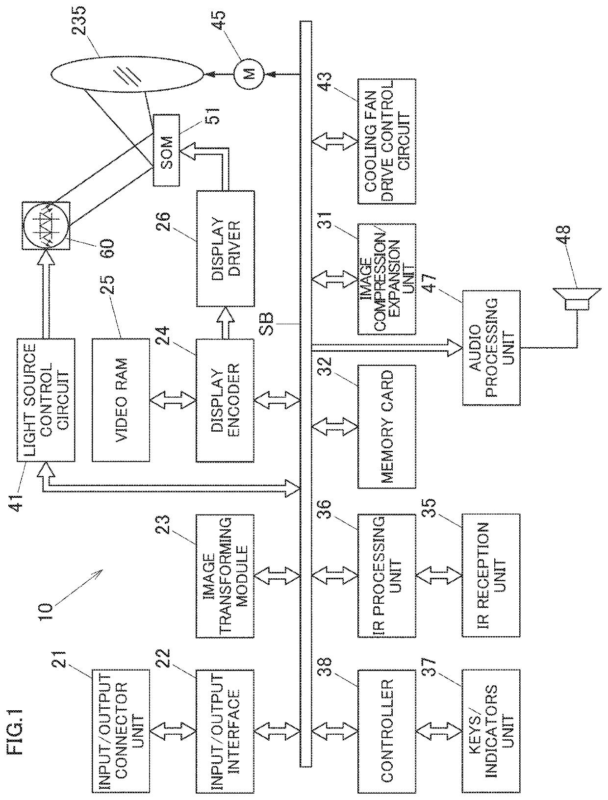
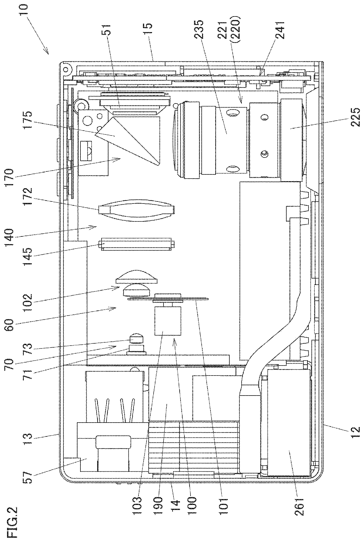
[0060]Next, a first modified example of the embodiment will be described based on FIG. 5. In this first modified example, the first luminescent material light emitting area 126R of the luminescent material light emitting area 126 on the second wheel 120 of the optical wheel 101 is eliminated, and a red light source device 80 is provided instead. The red light source device 80 includes a red laser diode 81, which is a second semiconductor light emitting device configured to emit laser light in the red wavelength range (light in a second wavelength range), and a collimator lens 83. The red laser diode 81 is disposed in such a manner that an optical axis of the red laser diode 81 intersects an optical axis of a blue laser diode 71 at right angles. A dichroic mirror 141 is provided in a position where the optical axis of the red laser diodes 81 intersects the optical axis of the blue laser diode 71 at right angles. The dichroic mirror 141 transmits light in the blue wavelength range and...
second modified example
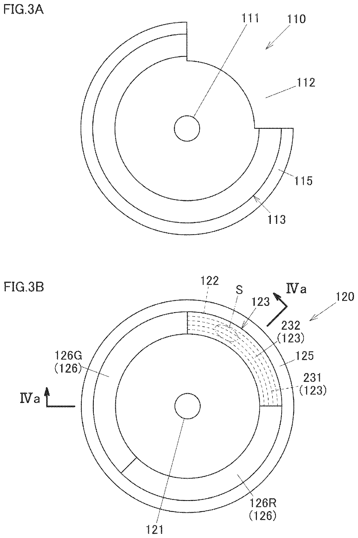
[0062]Next, a second modified example of the embodiment will be described based on FIG. 6A. In the second modified example, an optical wheel 101B is provided in which a second wheel 120B is formed by use of a controlling and diffusing optical area 123B made up of a controlling and diffusing member into which a controlling section 231B and a diffusing section 232B are integrated in place of the controlling and diffusing optical area 123 of the embodiment described above. The number of surfaces on which light is incident (specifically, surfaces where the controlling section 231 and the diffusing section 232 are joined together) can be reduced by integrating the controlling section 231B, which is a cylindrical lens array including a plurality of cylindrical lenses CL whose radial cross section is recessed (formed into a recessed arc-like shape), and the diffusing section 232B, whereby the loss of incident light can be reduced.
third modified example
[0063]Next, a third modified example will be described based on FIG. 6B. In the third modified example, an optical wheel 101C is provided. The optical wheel 101C includes a second wheel 120C having a controlling and diffusing optical area 123C including a controlling section 231C that is a cylindrical lens array including a plurality of cylindrical lenses CL whose radial cross section is convexly protuberant (formed into a protuberant arc-like shape) in place of the controlling section 231 of the controlling and diffusing optical area 123 of the embodiment described above.
PUM
| Property | Measurement | Unit |
|---|---|---|
| wavelength range | aaaaa | aaaaa |
| shape | aaaaa | aaaaa |
| spreading angle | aaaaa | aaaaa |
Abstract
Description
Claims
Application Information
 - R&D
- Intellectual Property
- Life Sciences
- Materials
- Tech Scout
- Unparalleled Data Quality
- Higher Quality Content
- 60% Fewer Hallucinations
Browse by: Latest US Patents, China's latest patents, Technical Efficacy Thesaurus, Application Domain, Technology Topic, Popular Technical Reports.
© 2025 PatSnap. All rights reserved.Legal|Privacy policy|Modern Slavery Act Transparency Statement|Sitemap|About US| Contact US: help@patsnap.com


