

Circuit board structure and conductive transmission line structure thereof
- Summary
- Abstract
- Description
- Claims
- Application Information
AI Technical Summary
Benefits of technology
Problems solved by technology
Method used
Image

Examples
Embodiment Construction
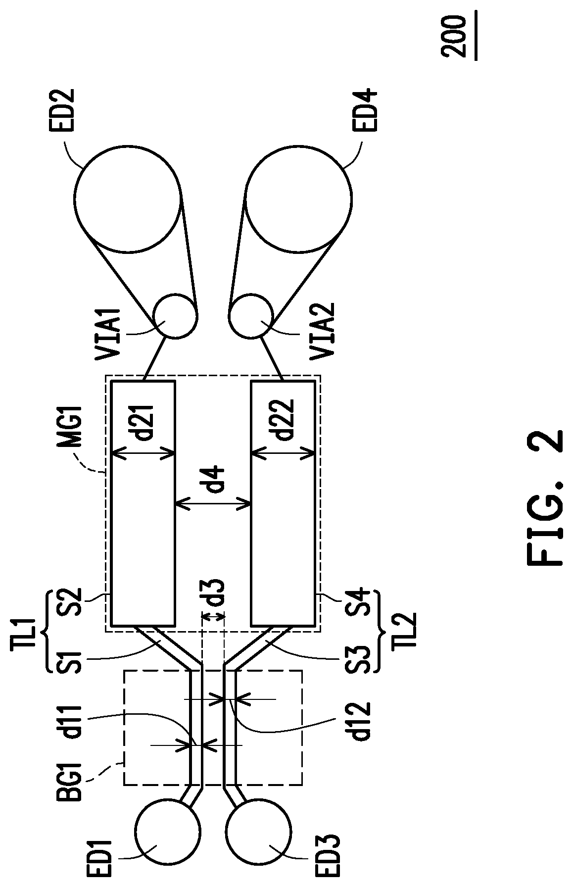
[0021]Please refer to FIG. 2. FIG. 2 is a schematic diagram of a conductive transmission line structure according to an embodiment of the invention. A conductive transmission line structure 200 includes conductive transmission lines TL1 and TL2. The conductive transmission line TL1 consists of segment S1 and segment S2, and the conductive transmission line TL2 consists of segment S3 and segment S4. The segment S1 and the segment S2 are sequentially connected between the signal transmission nodes ED1 and ED2. Segment S3 and segment S4 are sequentially connected between the signal transmission nodes ED3 and ED4. It should be noted that the segment S1 of the conductive transmission line TL1 is disposed adjacent to the segment S3 of the conductive transmission line TL2 to form a bridge segment BG1. The segment S2 of the conductive transmission line TL1 is adjacent to the segment S4 of the conductive transmission line TL2 to form a main transmission segment MG1 for transmitting signals.
[...
PUM
 Abstract
Description
Claims
Application Information