
Connection Clamping Device

a clamping device and connection technology, applied in the direction of hose connection, coupling, biochemical apparatus and processes, etc., can solve the problems of uneven compression of flexible tubes, damage to sensitive materials provided in the vicinity, and sharp edges, so as to prevent damage to bioprocesses, facilitate connection and reliable, the effect of fast and easy mounting

Active Publication Date: 2020-04-09
GLOBAL LIFE SCI SOLUTIONS USA LLC
View PDF0 Cites 5 Cited by
  • Summary
  • Abstract
  • Description
  • Claims
  • Application Information

AI Technical Summary

Benefits of technology

The invention relates to a connection clamping device for securely attaching flexible tubes to tube connectors in bioprocess assemblies. The device is easy to use, leak-proof, and reliable, with high precision in the connection. The method allows for fast and easy connection of flexible tubes to tube connectors with a reliable connection. The device has rounded surfaces to prevent damage to sensitive disposables and includes a locking mechanism to compress the flexible tube against the tube connector during connection. Overall, the invention provides a faster, easier, and more secure way to connect flexible tubes in bioprocess assemblies.

Problems solved by technology

There are some drawbacks related to the use of cable ties in this context.
One problem is that the compression of the flexible tube will not be evenly distributed over the whole circumference because of the head of the cable tie.
Under the head of the cable tie the flexible tube will “bubble up” and this could cause leakage.
Another problem is that the strap of the cable tie which is left pointing out from the head after tightening is somewhat sharp, particularly if it is the remaining part of a cut-off strap, and could possibly damage sensitive materials provided in vicinity.
Still a further problem with the use of cable ties is that it is rather time consuming.
One problem with this device is that these parts need to be slid over the flexible tube which can be tricky, especially since one of them fits close to the tube, i.e. the inner diameter of one of the parts is almost the same as the tube outer diameter.
Furthermore, the use of a tool is both tricky, it needs some force and precision, and time consuming.

Method used


Image

  • Connection Clamping Device
  • Connection Clamping Device
  • Connection Clamping Device

Examples


Embodiment Construction

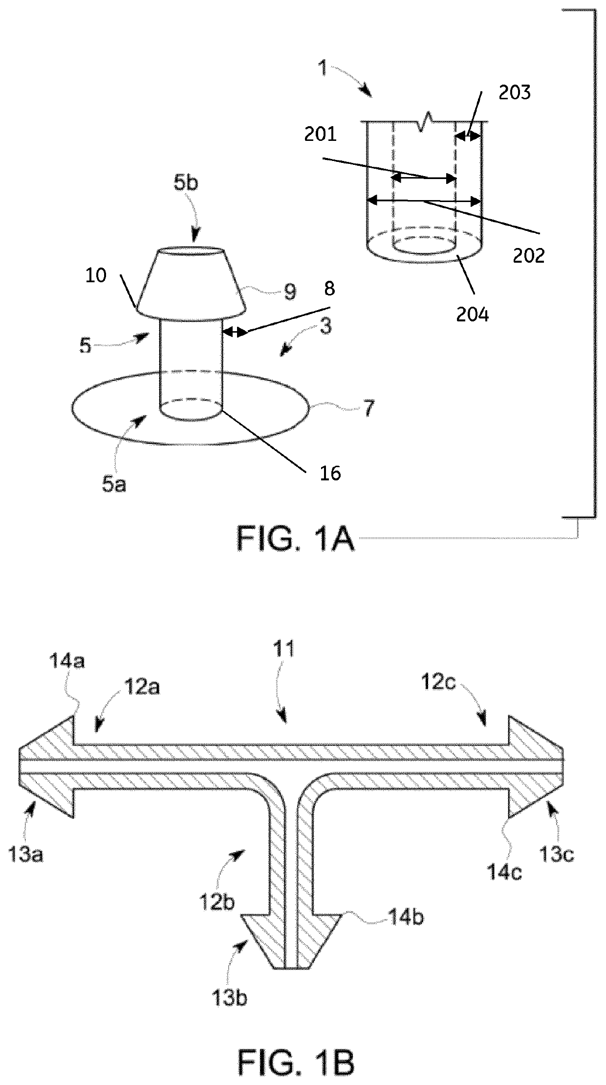
[0045]FIG. 1a shows schematically a flexible tube 1, with inner diameter 201, outer diameter 202, wall thickness 203 and tube end 204, and a port 3. This kind of port 3 could be provided onto for example bags that need to be connected to other components such as flexible tubes. When connecting the flexible tube 1 to the port 3 the tube is simply slid over a tube connector 5 of the port 3. The tube connector 5 of the port 3 has the form of a short tube and is connected to a sealing part 7 of the port 3 in a first (proximal) end 5a of the tube connector 5. The sealing part 7 of the port 3 is in this embodiment shown to extend around the first end 5a of the tube connector 5 in a perpendicular direction to the tube extension. The sealing part is adapted to be sealed, e.g. by welding, to the device that should be connected to the flexible tube 1, such as for example a flexible bioprocess bag. A second (distal) end 5b of the tube connector 5, which is positioned on the other end of the tu...


PUM


Abstract

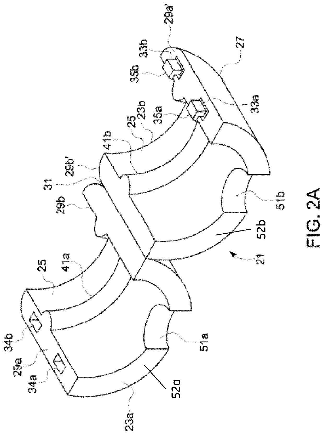
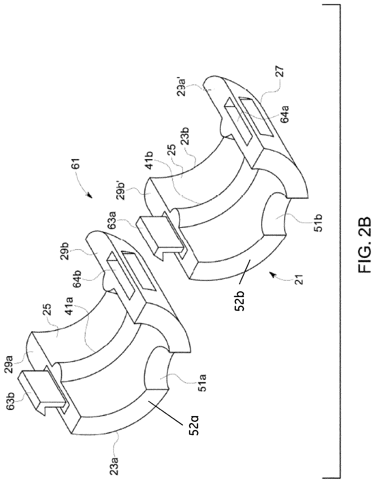
A connection clamping device (21; 61; 81; 131; 151) arranged for securing a flexible tube (1) to a barbed end (5b) of a tube connector (5), whereby the barbed end (5b) comprises a barb (9) and the tube connector during connection is arranged to protrude into an end of the flexible tube (1), characterized in that said connection clamping device comprises two sections (23a, 23b) which, during connection when the tube connector protrudes into an end of the flexible tube, are arranged to be connected and locked to each other by a locking mechanism (33a,33b,34a,34b; 63a, 63b, 64a, 64b) around the tube connector (5) and the flexible tube (1), such that the flexible tube (1) is compressed against the tube connector (5) by a rib (41a, 41b) provided on the inner circumference of the connection clamping device.

Description

TECHNICAL FIELD OF THE INVENTION[0001]The present invention relates to a connection clamping device for use with disposable bioprocess assemblies and to a method for securing flexible tubes to tube connectors during the manufacture of disposable bioprocess assemblies. It also relates to a disposable bioprocess assembly with one or more connection clamping devices and to a method of bioprocessing using such assemblies.BACKGROUND OF THE INVENTION[0002]Flexible tubing / tubes are used for transferring fluids or gases in many different environments for example in bioprocessing, medical and food industry. The flexible tubing needs to be connected to different components such as for example bags, sensors, fittings, ports or couplings of different types. Especially in for example the medical field and the bioprocessing field it is highly important that these connections are leak proof and that no liquid will get trapped in the connection causing for example growth of bacteria.[0003]A tube co...

Claims


Application Information

Patent Timeline
Patent Type & Authority Applications(United States)
IPC IPC(8): A61M39/12F16L33/23F16L33/035
CPCA61M39/12A61M2039/1066F16L2201/10F16L33/035F16L2201/44C12M23/28F16L33/23C12M23/00F16L33/02
Inventor STANKOWSKI, RALPHTUOHEY, COLIN R.TENANDER, ERICBARRIEAU, ETHAN MICHAEL
Owner GLOBAL LIFE SCI SOLUTIONS USA LLC
Learn More