Electrically driven vehicle

a technology of electric motors and electric motors, applied in hybrid vehicles, vehicle sub-unit features, battery/fuel cell control arrangements, etc., can solve the problems of insufficient investigation of problems such as the inability of voltage converters to operate appropriately

Active Publication Date: 2020-04-09
HONDA MOTOR CO LTD
View PDF0 Cites 6 Cited by
  • Summary
  • Abstract
  • Description
  • Claims
  • Application Information

AI Technical Summary

Benefits of technology

[0007]The present disclosure provides an electrically driven vehicle in which a charging current or a discharging current can be prevented from f

Problems solved by technology

Therefore, when charging or discharging is performed, for example, in a state where the closed-circuit voltages of two power storage devices are approximate to each other, there are cases where the voltage con

Method used


Image

  • Electrically driven vehicle
  • Electrically driven vehicle
  • Electrically driven vehicle

Examples


first embodiment

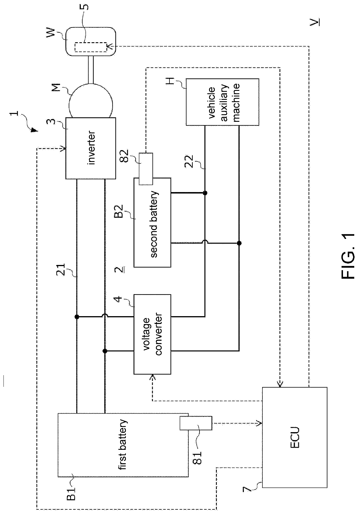
[0022]Hereinafter, the first embodiment of the present disclosure will be described with reference to the drawings. FIG. 1 is a view illustrating a configuration of an electrically driven vehicle V (which will hereinafter be simply referred to as “a vehicle”) according to the present embodiment. The vehicle V includes a power supply system 1, a drive motor M that is an electric motor, a mechanical braking device 5, a driving wheel W, and an electronic control device 7 (hereinafter, an abbreviation of “ECU” will be used) which controls the power supply system 1, the drive motor M, and the mechanical braking device 5. The control device (ECU) 7 may include a processor (or processing circuit, CPU) and its cooperative components or circuit such as memory (ROM, RAM, etc.) to executes control programs for controlling the operations of the respective components of the vehicle V and carry out control processes described below.

[0023]The drive motor M mainly generates a dynamic force for the ...

second embodiment

[0101]Hereinafter, a vehicle according to a second embodiment of the present disclosure will be described with reference to the drawings.

[0102]FIG. 8 is a view illustrating a configuration of a vehicle VA according to the present embodiment. The vehicle VA according to the present embodiment differs from the vehicle V according to the first embodiment in a configuration of a power supply system 1A. More specifically, the vehicle VA differs in configurations of a connection position of a vehicle auxiliary machine HA, ranges of use of a first battery BA1 and a second battery BA2, a voltage converter 4A, and an ECU 7A. In the following description of the present embodiment, the same reference signs are applied to the same constitutions as the first embodiment and detailed description thereof will be omitted. Points different from the first embodiment will be described. In the present embodiment, the vehicle auxiliary machine HA is connected to the first power line 21 between the second...


PUM


Abstract

A vehicle includes an inverter, a first battery, a first power line, a second battery, a second power line, and a voltage converter. Ranges of use with respect to open circuit voltages of the first battery and the second battery do not overlap each other, and ranges of use with respect to closed circuit voltages of the first and the second batteries overlap each other. When a regenerative power output from the inverter to the first power line is supplied to the second power line via the voltage converter, and the second battery is charged, an ECU calculates a maximum regenerative power with respect to the regenerative power output from the inverter to the first power line based on the open circuit voltage of the first battery and controls the inverter and the voltage converter such that the regenerative power does not exceed the maximum regenerative power.

Description

CROSS-REFERENCE TO RELATED APPLICATION[0001]This application claims the priority of Japan patent application serial no. 2018-190831, filed on Oct. 9, 2018. The entirety of the above-mentioned patent application is hereby incorporated by reference herein and made a part of this specification.BACKGROUNDTechnical Field[0002]The present disclosure relates to an electrically driven vehicle. More specifically, the present disclosure relates to an electrically driven vehicle including two power storage devices differing from each other in a range of use with respect to a voltage, and a voltage converter converting a voltage between circuits in which these two power storage devices are provided.Description of Related Art[0003]Electrically driven vehicles travel by supplying power stored in a power storage device such as a secondary battery or a capacitor to a drive motor and rotating a driving wheel. In addition, in an electrically driven vehicle, the drive motor functions as a generator du...

Claims


Application Information

Patent Timeline
IPC IPC(8): B60L58/18H02J7/00H02K47/04B60W30/18B60W20/14
CPCB60L58/18B60W20/14H02K47/04H02J7/007B60W30/18127B60L50/60B60L15/007H02J2310/48H02J7/342H02J7/1423Y02T10/70Y02T10/7072Y02T90/14B60W10/08B60W10/18B60W10/26B60W2540/10B60W2540/12B60W2710/248B60W2710/083B60W2710/18B60W2510/305B60W2510/242B60Y2400/61
Inventor OGUMA, HIROKAZU
Owner HONDA MOTOR CO LTD
Why Eureka
Try Eureka