Passive electroseismic surveying

a surveying and electroseismic technology, applied in the direction of acceleration measurement in multiple dimensions, acceleration measurement using interia forces, instruments, etc., can solve the problems of limiting economic viability, requiring the use of expensive and/or time-consuming surveying equipment, and preventing a full understanding of the geophysical properties of prospective regions. the effect of reducing the disadvantages and eliminating the problems of conventional geophysical surveying techniques

Inactive Publication Date: 2020-04-09
ES XPLORE L L C
View PDF0 Cites 13 Cited by
  • Summary
  • Abstract
  • Description
  • Claims
  • Application Information

AI Technical Summary

Benefits of technology

[0002]In accordance with the teachings of the present disclosure, disadvantages and problems associated with conventional geophysical surveying techniques may be reduced and / or eliminated. For example, a surveying system may be provided using passive electroseismic or seismoelectric surveying techniques. The surveying system may utilize survey data from passive electroseismic or seismoelectric surveying and survey data from other geophysical surveying methods to determine one or more properties of a subsurface earth formation.

Problems solved by technology

These conventional surveying technologies, suffer from certain limitations that may prevent a full understanding of the geophysical properties of prospective regions.
For example, particular surveying techniques may require the use of expensive and / or time consuming surveying equipment and methods that may limit the economic viability of surveying a particular prospective region.
In addition, particular surveying technologies may be able to provide information regarding one or more geophysical properties of a subsurface region, but may not be able to provide information on other geophysical properties.
Such limitations may lead to the identification of prospective regions for drilling or exploration based on an incomplete and / or incorrect understanding of the prospective region, which may cause unnecessary time and / or expenses to be incurred exploring or drilling regions that do not have the desired geophysical properties.

Method used


Image

  • Passive electroseismic surveying
  • Passive electroseismic surveying
  • Passive electroseismic surveying

Examples


Embodiment Construction

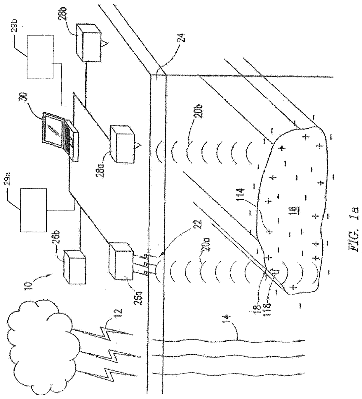
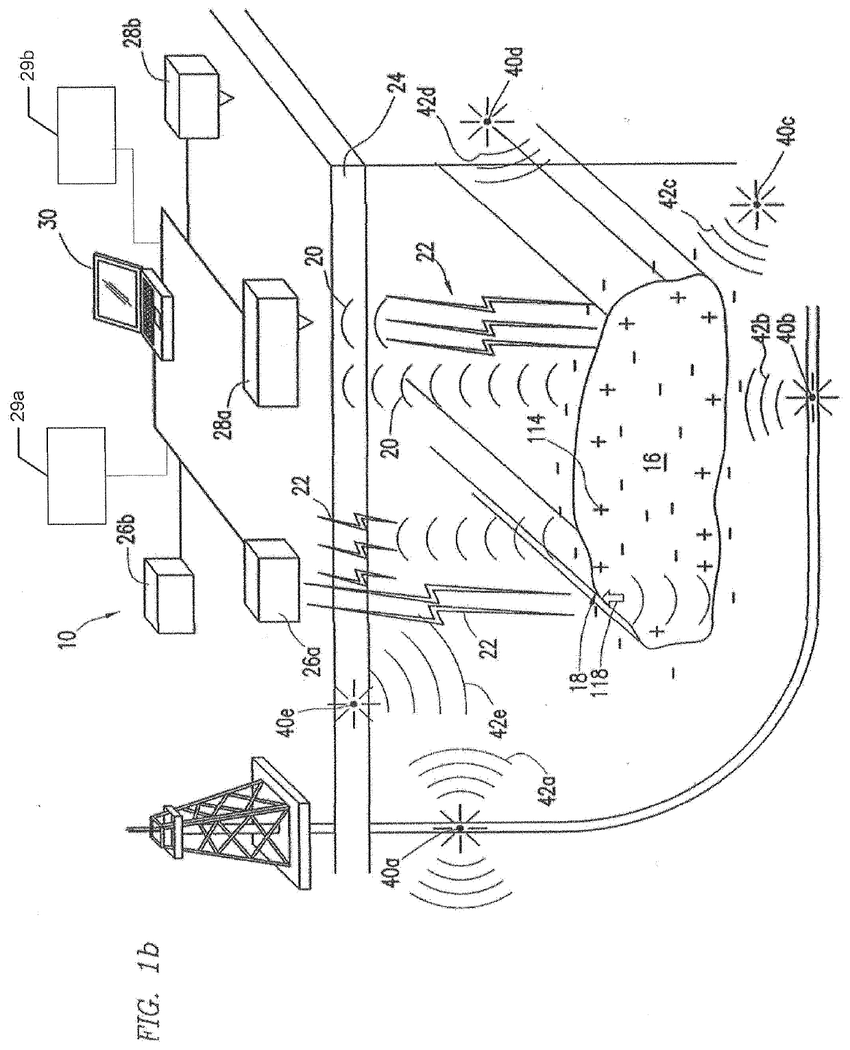
[0023]The example embodiments herein may utilize passive surveying techniques that utilize passive sources, such as naturally occurring electromagnetic fields and / or seismic waves, and the interactions of electromagnetic or seismic signals generated by those sources with subsurface formations through electroseismic and / or seismoelectric conversions to identify features and / or properties of subsurface earth formations. Such surveying may be useful for a variety of purposes, including the identification of subsurface water and minerals. While passive surveying may be suitable for use as a standalone method of geophysical surveying, passive surveying may, in some embodiments, be performed in conjunction with other geophysical surveying methods to identify properties of subsurface earth formations. The teachings of the present disclosure are intended to encompass embodiments that employ passive surveying as a standalone surveying technique as well as embodiments that use passive surveyi...


PUM


Abstract

A system for surveying a subsurface formation includes one or more electromagnetic sensors located at or above the surface of the Earth. The sensors are configured to detect passive-source source signals and return signals that are based on seismoelectric or electroseismic conversion of the source signal in the subsurface formation. The system includes a processor communicatively coupled to the one more electromagnetic sensors. The at least one processor is configured to align and stack the passive-source source signals and the return signals and determine a property of the subsurface formation based, at least in part, on the aligned and stacked passive-source source signals and the return signals.

Description

BACKGROUND OF THE INVENTION[0001]Conventional geophysical surveying techniques rely on various surveying technologies to identify prospective regions for drilling or exploration. These conventional surveying technologies, suffer from certain limitations that may prevent a full understanding of the geophysical properties of prospective regions. For example, particular surveying techniques may require the use of expensive and / or time consuming surveying equipment and methods that may limit the economic viability of surveying a particular prospective region. In addition, particular surveying technologies may be able to provide information regarding one or more geophysical properties of a subsurface region, but may not be able to provide information on other geophysical properties. Such limitations may lead to the identification of prospective regions for drilling or exploration based on an incomplete and / or incorrect understanding of the prospective region, which may cause unnecessary ...

Claims


Application Information

Patent Timeline
Patent Type & Authority Applications(United States)
IPC IPC(8): G01V1/30G01P15/18G01V1/18G01V1/24
CPCG01V2210/66G01P15/18G01V2210/324G01V1/181G01V1/247G01V2210/62G01V2210/1425G01V1/306G01V11/007
Inventor XU, LIYUTHOMPSON, ARTHUR HOWARDAULT, THOMAS CLAYTONENGLAND, ROBERT W.KATZ, ALAN JERRYRAHMAN, MOHAMMAD T.REESE, PATRICK LAWLER
Owner ES XPLORE L L C
Why Eureka
Try Eureka