Corrugated Washer for Use with a Corrugated L-Foot Mounting Bracket for Mounting Solar Panels to a Roof

Active Publication Date: 2020-04-16
UNIRAC INC
View PDF18 Cites 17 Cited by
  • Summary
  • Abstract
  • Description
  • Claims
  • Application Information

AI Technical Summary

Benefits of technology

[0002]A corrugated washer is used with a corrugated L-foot mounting bracket and a structural mounting rail for preventing vertical shear at the joint between the rail and the corrugated L-foot bracket, when mounting photovoltaic modules (i.e., solar panels) to a

Problems solved by technology

A problem with prior art joints between structural rails and mounting brackets (e.g., L-foot mounting brackets) is that excessive vibrations, aging, or improper installation torque can result in vertical slippage of the joint due to loosening of the attachment hardware (e.g., T-bolt) when the joint is subjecte

Method used


Image

  • Corrugated Washer for Use with a Corrugated L-Foot Mounting Bracket for Mounting Solar Panels to a Roof
  • Corrugated Washer for Use with a Corrugated L-Foot Mounting Bracket for Mounting Solar Panels to a Roof
  • Corrugated Washer for Use with a Corrugated L-Foot Mounting Bracket for Mounting Solar Panels to a Roof

Examples


first embodiment

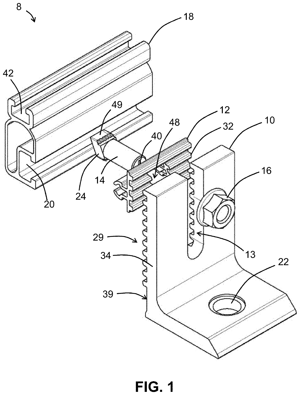
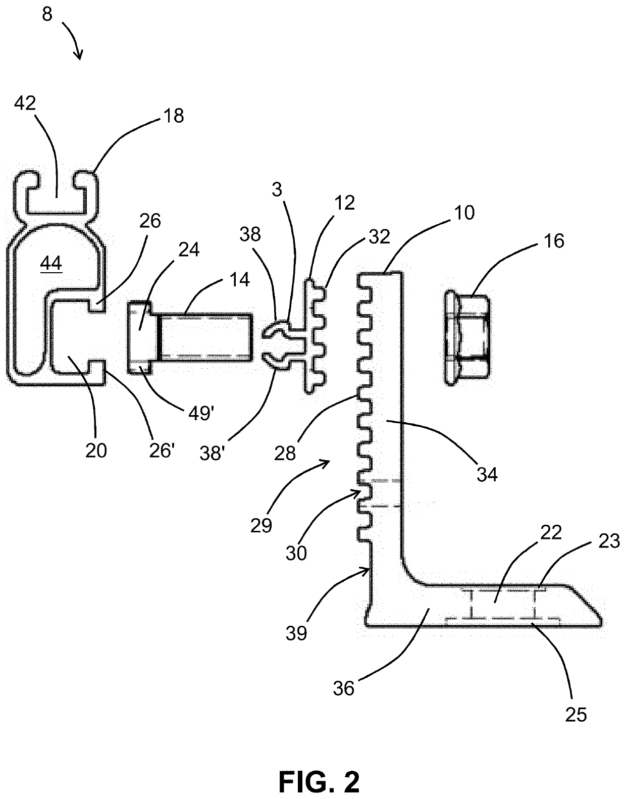
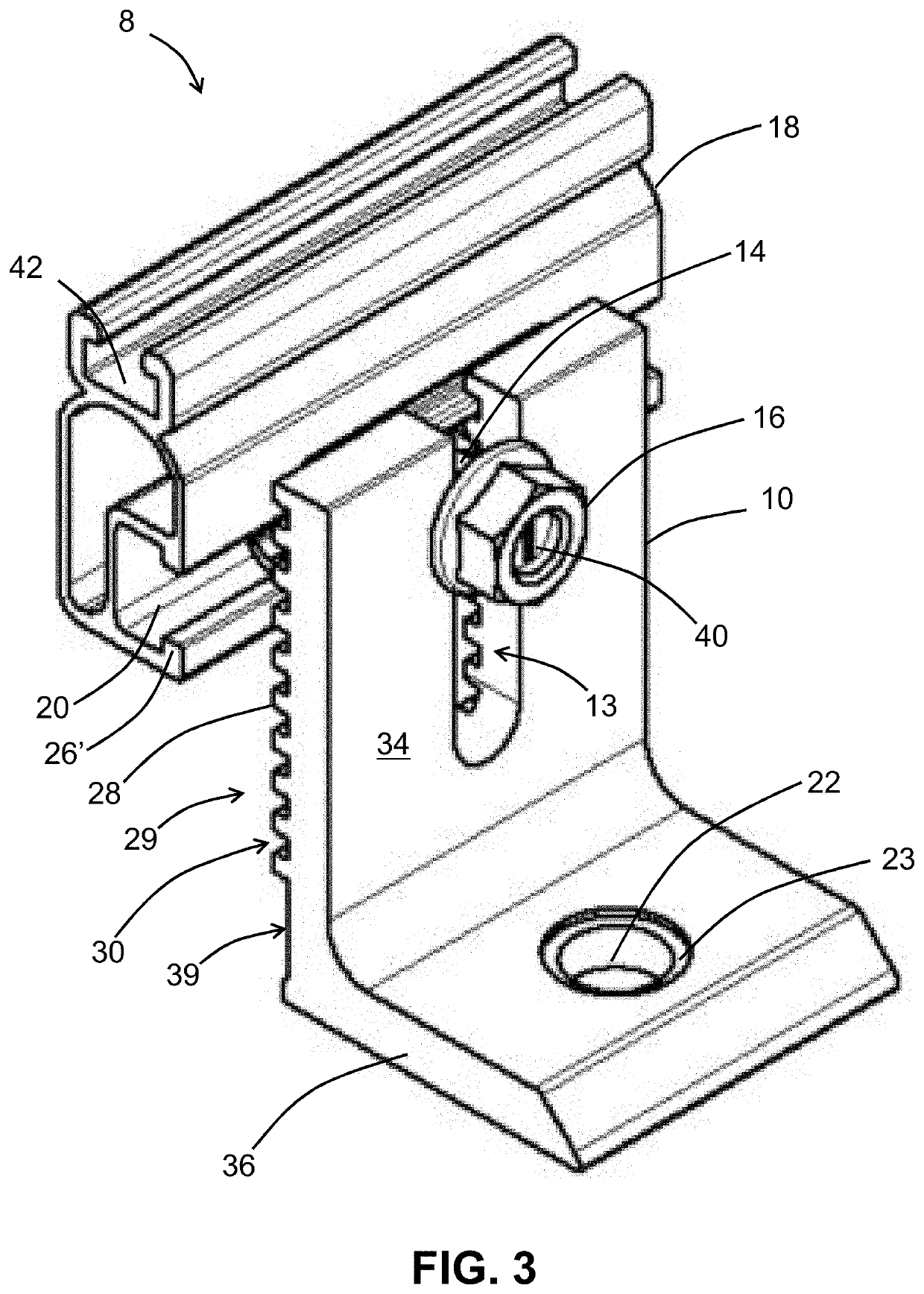
[0044]FIG. 1 shows an exploded perspective view of an assembly 8 comprising a corrugated washer 12 for use with a corrugated L-foot mounting bracket 10 and a solar panel mounting rail 18, according to the present invention. L-foot mounting bracket 10 is attached to a roof or other structure using a lag screw (not shown) passing through aperture 22. Corrugated washer 12 is disposed in-between L-foot bracket 10 and rail 18; and T-bolt 14 passes through aperture 48 in corrugated washer 12 and through U-shaped channel 13 in L-foot 10 (which provides for vertical height adjustment of the mounting rail 18 relative to the fixed L-foot 10 in discrete (fixed) height increments defined by the spacing between adjacent corrugations 29. T-bolt 14 (with T-shaped head 24) attaches structural mounting rail 18 to L-foot bracket 10 by inserting shoulders 49, 49′ (FIG. 2) of the head 24 of T-bolt 14 into the lower horizontal channel 20 of rail 18, and by tightening nut 16 on the threaded shaft of bolt...

second embodiment

[0063]FIG. 16 shows a rear perspective view of an assembly 110 comprising a corrugated washer 62 and a corrugated L-foot bracket 60, according to the present invention. L-foot 60 has a U-shaped vertical channel 66 for accepting a T-bolt (not shown). L-foot bracket 60 comprises a plurality of horizontal, uniformly-spaced, parallel corrugations 68 that span the width of L-foot 60. Corrugations 68 are disposed on the interior (inside) rear-facing surface 63 of the upper vertical leg 61 of L-foot 60. In this example, corrugations 68 are sinusoidal-shaped (wavy). Washer 62 has an aperture 70; matching interlocking corrugations 71 (FIG. 17); and a horizontal upper flange 112 for aiding in holding onto washer 62 when being placed into its operational position. Washer 62 has five corrugations 71, but any number from 1-12, for example, can be used. L-foot 60 has thirteen full-corrugations, but any number from 1-20, for example, can be used. Aperture 64 in base 65 is surrounded by a concentri...

third embodiment

[0065]FIG. 18 shows a rear perspective view of an assembly 120 comprising a corrugated washer 122 and a corrugated L-foot bracket 80, according to the present invention. L-foot bracket 80 comprises a plurality of horizontal, uniformly-spaced, parallel corrugations 88 that span the width of L-foot 80. L-foot 80 has a U-shaped vertical channel 86 for accepting a T-bolt (not shown). Corrugations 88 are disposed on the interior (inside) rear-facing surface 90 of the upper vertical leg 81 of L-foot 80. In this example, corrugations 88 are square-shaped. Washer 122 has a central aperture for accepting a T-bolt (not shown); and a mating pair of interlocking corrugations 82 and 82′ (FIG. 19). Nut 86 (called a “Keps” nut) has an attached circular swaged flange 83 that is rotationally coupled to washer 122. In other words, nut 86 has a free-spinning washer 122 attached to it. L-foot 80 has ten full-corrugations, but any number from 1-20, for example, can be used. Aperture 84 in base 85 is sur...


PUM


Abstract

A corrugated washer for use with a corrugated L-foot mounting bracket and a structural mounting rail prevents vertical shear at the joint between the rail and the corrugated L-foot bracket when mounting photovoltaic modules (i.e., solar panels) to a roof of a building or other structure. The design locks the T-bolt from falling off the rail slot, and always aligns the T-bolt in the correct orientation and prevents back-rotation. The corrugations on the washer and L-foot help for making height adjustments, too.

Description

BACKGROUND OF THE INVENTION[0001]The present invention relates to structures and methods for mounting one or more photovoltaic modules (i.e., solar panels) to a roof of a house or building, or other structure, using components made of stainless steel and / or aluminum alloys (which can be anodized). A problem with prior art joints between structural rails and mounting brackets (e.g., L-foot mounting brackets) is that excessive vibrations, aging, or improper installation torque can result in vertical slippage of the joint due to loosening of the attachment hardware (e.g., T-bolt) when the joint is subjected to shear forces due to wind loads, dead weight, etc. acting on the solar panels. Also, loosening of the hardware and vibrations can result in back-rotation of the T-bolt to a point where the head of the T-bolt can completely pull out of the slot in the rail, resulting in catastrophic failure of the structure. Finally, it is desirable to have a vertical height adjustment in the mount...

Claims


Application Information

Patent Timeline
IPC IPC(8): F16B39/24H02S20/23
CPCH02S20/23F16B39/24F16B5/0225F16B5/0233F16B5/0664F16B37/045F24S25/30F24S25/61F24S25/65F24S25/70F24S2025/6004F24S2025/6008F24S2025/801F24S2025/807Y02B10/10Y02B10/20Y02E10/47Y02E10/50F16B43/00H02S20/00
Inventor UPPU, SAIGANSHAW, TODD
Owner UNIRAC INC
Why Eureka
Try Eureka