
Conductive member for touch panel and touch panel

a technology of conductive members and touch panels, which is applied in the direction of dielectric characteristics, conductive layers on insulating supports, instruments, etc., can solve the problems of insufficient assurance of intersections of fine metal wires compared to other second electrode regions, and it is not possible to obtain high detection sensitivity and excellent uniformity of detection sensitivity of touch panels, so as to improve detection sensitivity and improve detection sensitivity. the effect of uniformity

Active Publication Date: 2020-04-16
FUJIFILM CORP
View PDF0 Cites 2 Cited by
  • Summary
  • Abstract
  • Description
  • Claims
  • Application Information

AI Technical Summary

Benefits of technology

The present invention is a conductive member for a touch panel that improves detection sensitivity and uniformity of detection sensitivity for a touch operation. The conductive member includes multiple first electrodes, each consisting of a main electrode and a sub-electrode. The sub-electrodes have a smaller mesh pitch compared to the main electrodes, which ensures sufficient intersections of fine metal wires and prevents an increase in resistance value. This improves detection sensitivity and promotes a uniformity of detection sensitivity on the touch panel.

Problems solved by technology

However, in the touch panel disclosed in JP2012-073783A, a conductive member constituted using a fine metal wire that can be expected to have high detection sensitivity for an electrode pattern is employed, but it is not possible to obtain the touch panel having high detection sensitivity and an excellent uniformity of detection sensitivity.
Moreover, the third electrode in JP2014-203203A includes a portion having the same mesh pitch as a mesh pitch of the second electrode, but in this portion, the number of intersections of fine metal wires is not sufficiently ensured compared to regions of other second electrodes.

Method used


Image

  • Conductive member for touch panel and touch panel
  • Conductive member for touch panel and touch panel
  • Conductive member for touch panel and touch panel

Examples


embodiment 1

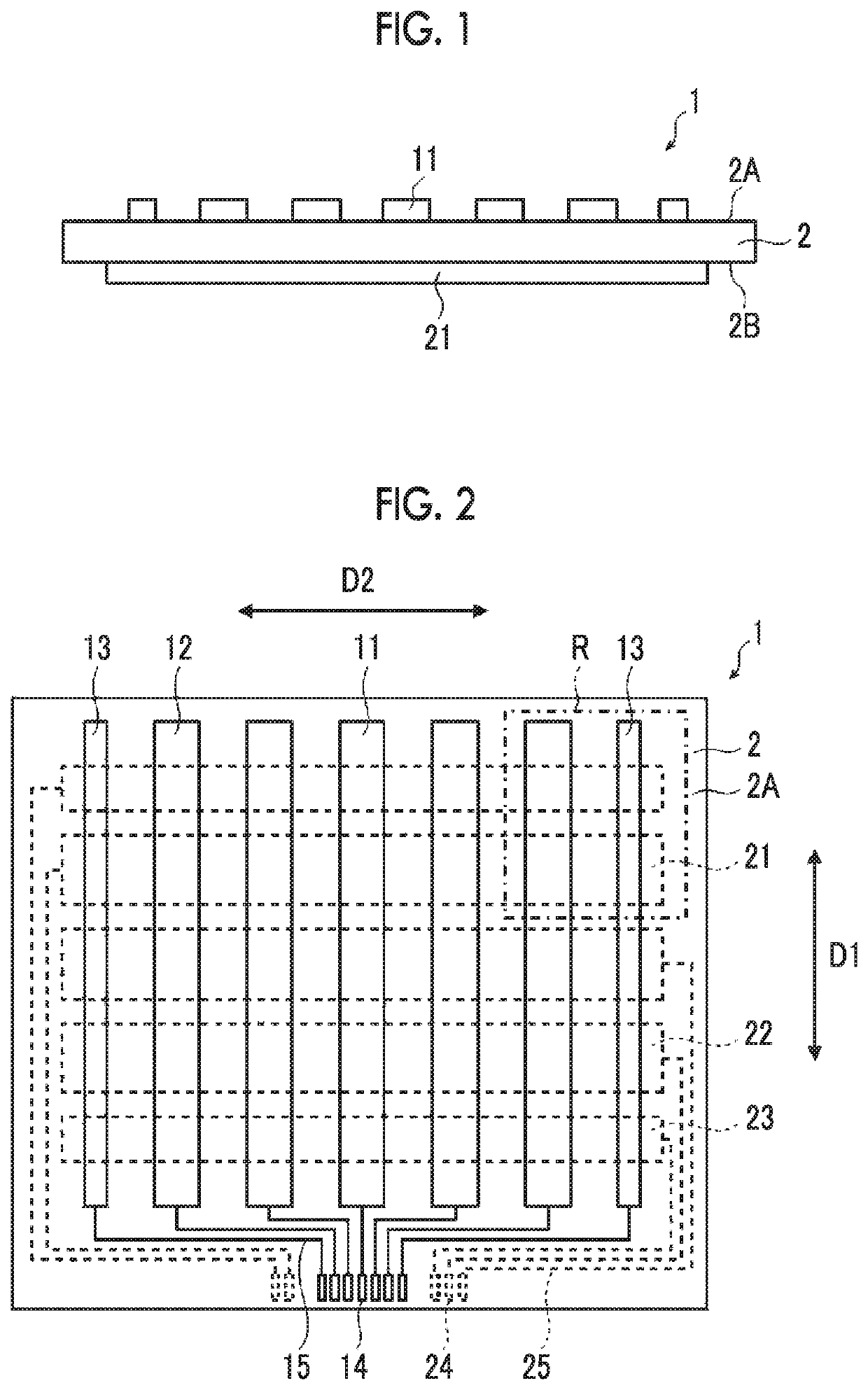
[0048]FIG. 1 is a cross section view showing a conductive member 1 according to Embodiment 1. As shown in FIG. 1, the conductive member 1 has a transparent insulating substrate 2 that is a transparent insulating member, and the transparent insulating substrate 2 has a front surface 2A and a back surface 2B. A plurality of first electrodes 11 are formed on the front surface 2A of the transparent insulating substrate 2, and a plurality of second electrodes 21 are formed on the back surface 2B of the transparent insulating substrate 2 as described later.

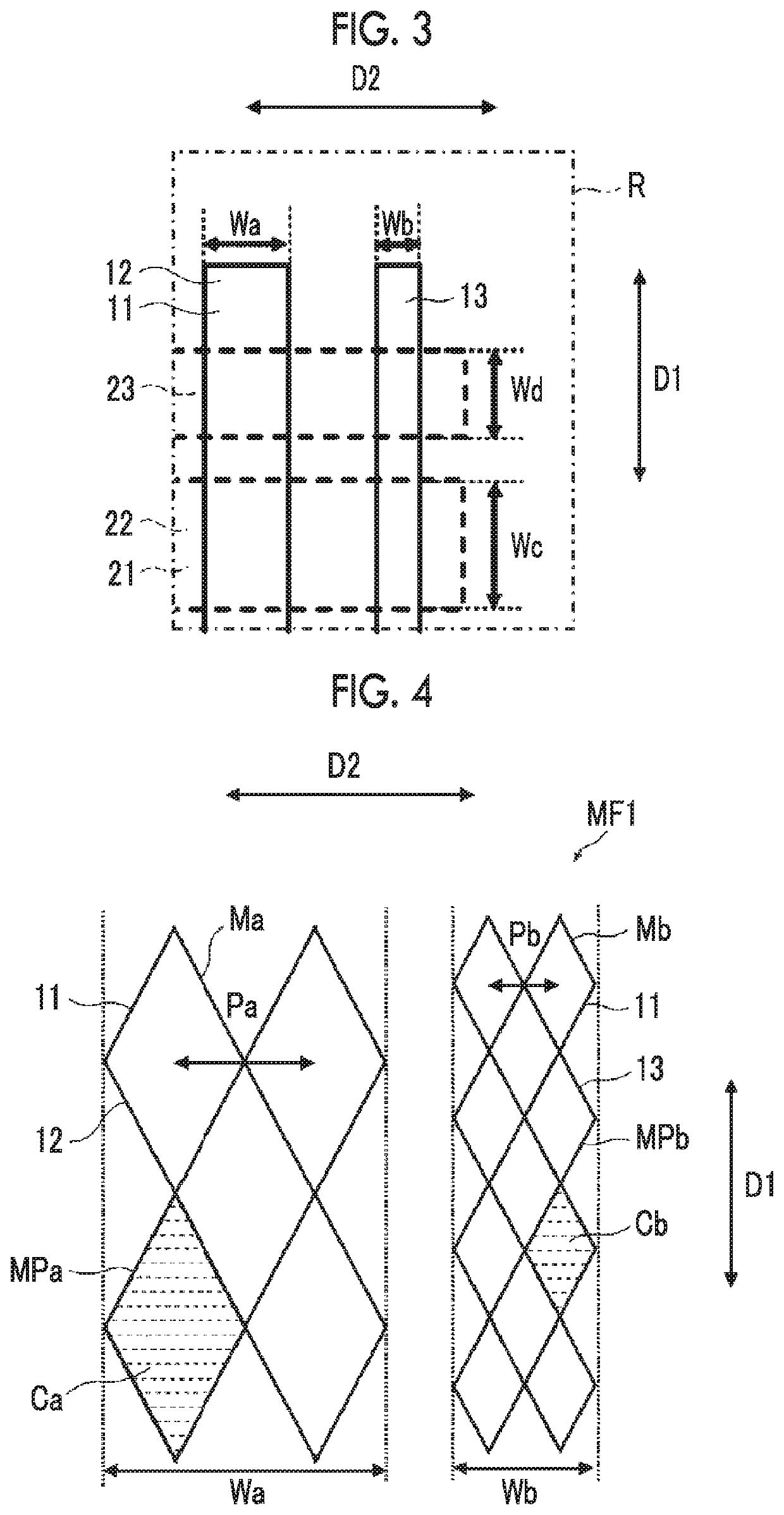
[0049]FIG. 2 is a plan view showing the conductive member 1 according to Embodiment 1. As shown in FIG. 2, the plurality of first electrodes 11 extend in a first direction D1 and are arranged in parallel at intervals therebetween in a second direction D2 intersecting the first direction D1 so as to be insulated from one another. In addition, the plurality of first electrodes 11 arranged in parallel in the second direction D2 include a p...

embodiment 2

[0103]FIG. 7 is a partially enlarged plan view of a first main electrode 42 and a first sub-electrode 13 in Embodiment 2. The first sub-electrode 13 of a first electrode 41 in Embodiment 2 is the same as the first sub-electrode 13 in Embodiment 1, and the first main electrode 42 of the first electrode 41 in Embodiment 2 is the same as the first main electrode 12 in Embodiment 1 except that a first dummy pattern DP1 is included. The first dummy pattern DP1 is constituted by a plurality of fine metal wires DM1, and the plurality of fine metal wires DM1 are arranged with a gap G1 with respect to a plurality of fine metal wires Ma constituting the first conductive mesh pattern MPa. That is, the first dummy pattern DP1 is arranged so as to be electrically insulated from the first conductive mesh pattern MPa. In addition, the first dummy pattern DP1 is arranged on a line connecting the midpoints of sides of the mesh cell Ca facing each other so that the mesh cell Ca constituting the first...

example 1

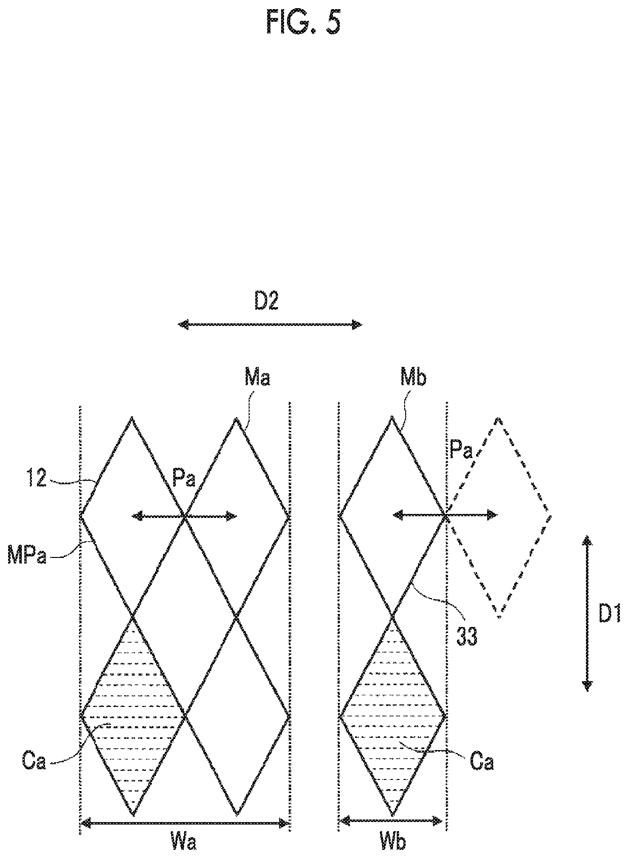
[0195]Example 1 is a touch panel having a conductive member of the same shape as that of the conductive member 1 of Embodiment 1 illustrated in FIGS. 1 to 4 and 6. The line width of each of the plurality of fine metal wires Ma and Mb constituting the plurality of first electrodes 11 and the plurality of second electrodes 21 is set to 4.0 μm, and the first conductive mesh pattern MPa and the second conductive mesh pattern MPb constituting the plurality of first electrodes 11, and the third conductive mesh pattern MPc and the fourth conductive mesh pattern MPd constituting the plurality of second electrodes 21 were a rhombus mesh with an acute angle of 60 degrees. In addition, in the first electrode 11, the mesh pitch Pa of the first conductive mesh pattern MPa constituting the first main electrode 12 was set to 800 μm, the electrode width Wa of the first main electrode 12 was set to 2.00 mm, the mesh pitch Pb of the second conductive mesh pattern MPb constituting the first sub-electr...


PUM


Abstract

A conductive member 1 for a touch panel includes a plurality of first electrodes 11 extending in a first direction and arranged in parallel in a second direction intersecting the first direction, in which the plurality of first electrodes are constituted by a first mesh conductive film MF1 constituted by a plurality of fine metal wires Ma, and include a plurality of first main electrodes each having a defined electrode width Wa and at least one first sub-electrode having an electrode width Wb smaller than the electrode width Wa of the first main electrode, and in which over an entire region of the first sub-electrode, a mesh pitch Pb of the first mesh conductive film MF1 constituting the first sub-electrode in the second direction is smaller than a mesh pitch Pa of the first mesh conductive film MF1 constituting the first main electrode in the second direction.

Description

CROSS-REFERENCE TO RELATED APPLICATIONS[0001]This application is a Continuation of PCT International Application No. PCT / JP2018 / 025178 filed on Jul. 3, 2018, which claims priority under 35 U.S.C. § 119(a) to Japanese Patent Application No. 2017-145673 filed on 2017 Jul. 27. Each of the above application(s) is hereby expressly incorporated by reference, in its entirety, into the present application.BACKGROUND OF THE INVENTION1. Field of the Invention[0002]The present invention relates to a conductive member for a touch panel.[0003]The present invention also relates to a touch panel obtained using a conductive member.2. Description of the Related Art[0004]In recent years, in various electronic devices including portable information devices such as tablet computers and smart phones, a touch panel which is used in combination with display devices such as liquid crystal display devices and which performs an input operation on an electronic device by causing members such as fingers and st...

Claims


Application Information

Patent Timeline
IPC IPC(8): G06F3/044H05K1/11H05K3/00H05K3/28
CPCG06F3/044G06F2203/04112H05K3/0014H05K1/119H05K3/28H01B5/14G06F3/0446G06F3/0445G06F3/0448H05K1/0274H05K2201/0108H05K2201/09681
Inventor NAKAYAMA, MASAYAKURIKI, TADASHIIKEDA, REONA
Owner FUJIFILM CORP
Learn More