Eureka AIR delivers breakthrough ideas for toughest innovation challenges, trusted by R&D personnel around the world.

Air intake grille and vehicle

Active Publication Date: 2020-04-23
HONDA MOTOR CO LTD
View PDF0 Cites 0 Cited by
  • Summary
  • Abstract
  • Description
  • Claims
  • Application Information

AI Technical Summary

Benefits of technology

The patent describes an air intake grille for a vehicle that has a flow rate adjusting plate with a smaller opening area than the grille itself. This reduces the flow velocity of the air, improving the comfort and reducing vibration for the passengers. The grille also prevents foreign objects from entering the intake port. The flow rate adjusting plate can be easily manufactured and installed, and the grille and intake port can be offset to adjust the flow velocity. Overall, the patent provides a technical solution for improving the performance and aesthetics of air intake grilles for vehicles.

Problems solved by technology

However, when a dust-proof filter is provided, pressure loss may occur and cooling efficiency may be reduced.

Method used


Image

  • Air intake grille and vehicle
  • Air intake grille and vehicle
  • Air intake grille and vehicle

Examples


Embodiment Construction

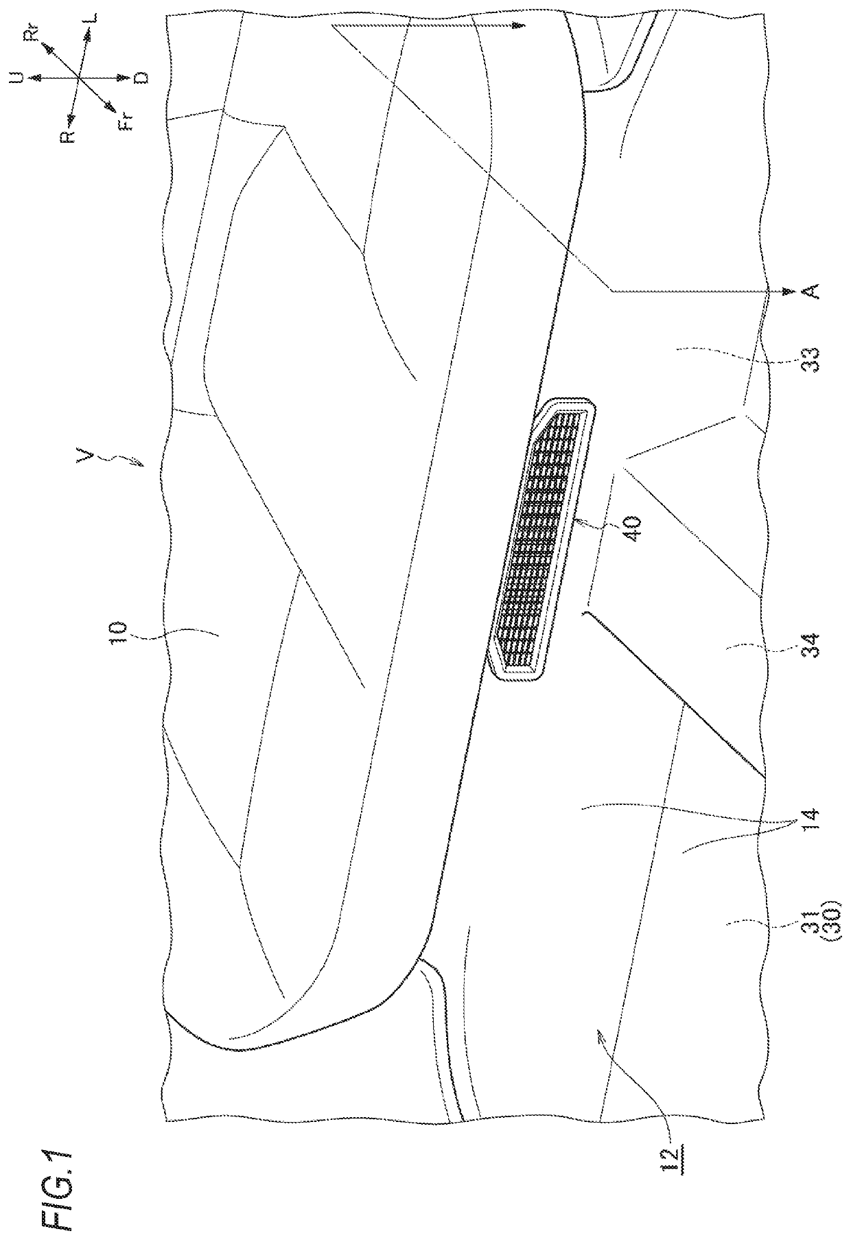
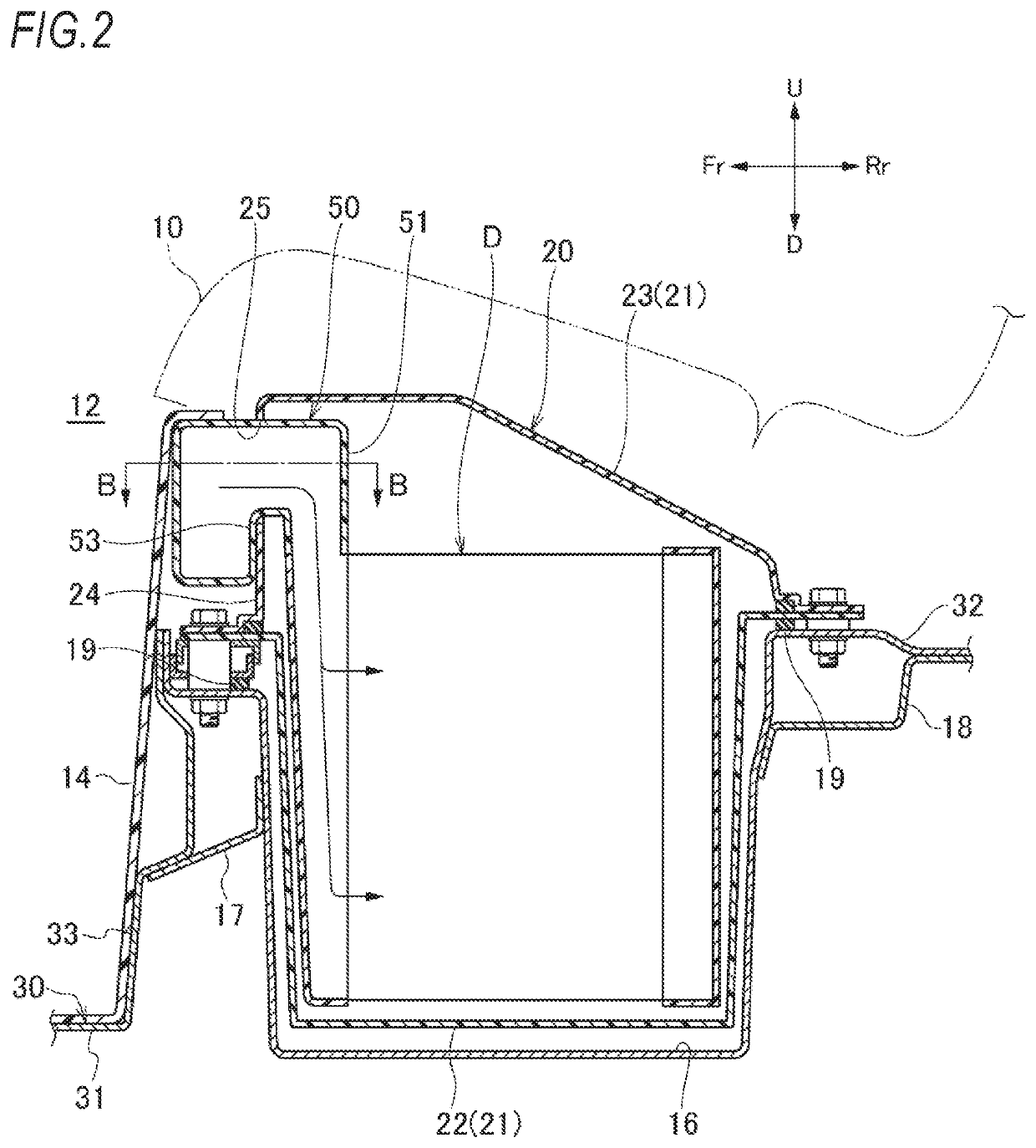
[0050]Hereinafter, an embodiment of the invention will be described with reference to the drawings. The drawings shall be viewed in directions of the reference letters. In the following description, front-rear, left-right, and up-down correspond to directions seen from a driver, and in the drawing, the front of the vehicle is indicated by Fr, the rear is Rr, the left is L, the right is R, the upper is U, and the lower is D.

[0051]A vehicle V of the embodiment illustrated in FIGS. 1 and 2 is an electric vehicle in which a battery unit 20 which accommodates a battery is mounted below a rear seat 10.

[0052]Floor Structure

[0053]As illustrated in FIG. 1 and FIG. 2, in a floor panel 30 of the vehicle V, a front floor panel 31 which constitutes a floor portion of a passenger compartment 12 and a rear floor panel 32 which constitutes a floor portion of a cargo compartment and the like are connected below the rear seat 10. In the drawing, reference numerals 14 denote a carpet which covers the ...


PUM


Abstract

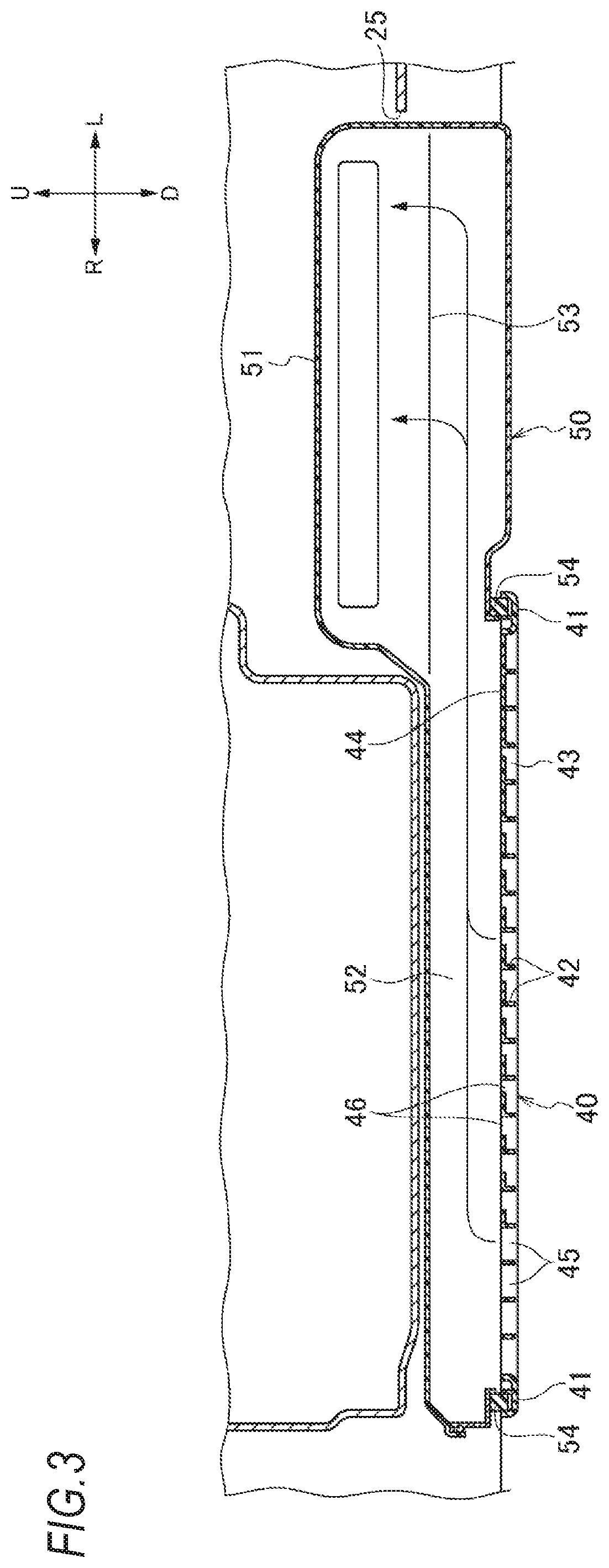
An air intake grille through which air in a passenger compartment of a vehicle V is taken in includes a frame body, a plurality of first grille forming portions and second grille forming portions arranged in a lattice shape inside the frame body, and a flow rate adjusting plate disposed inside the frame body so as to be perpendicular to the first grille forming portions and the second grille forming portions. The flow rate adjusting plate has a flow rate adjusting window having an opening area smaller than an opening portion inside the opening portion formed by the first grille forming portion and the second grille forming portion.

Description

TECHNICAL FIELD[0001]The present invention relates to an air intake grille through which air in a passenger compartment of a vehicle is taken in and a vehicle equipped with the air intake grille.BACKGROUND ART[0002]Battery units accommodating batteries (high-voltage batteries) for driving motors are mounted on electric vehicles such as hybrid electrical vehicles (HEVs) and electrical vehicles (EVs). This type of vehicle has a cooling structure for cooling the battery and an air cooling type cooling structure is widely adopted.[0003]For example, a vehicle has been known in which a battery unit is disposed under a seat of a passenger compartment and a battery is cooled by air (hereinafter referred to as air in the passenger compartment as appropriate) introduced from the passenger compartment into the battery unit. A dust-proof filter or the like is provided in an intake portion for taking in air in the passenger compartment in order to remove foreign objects or the likes. However, wh...

Claims


Application Information

Patent Timeline
IPC IPC(8): B60K11/06B62D25/20B60K1/04
CPCB60K11/06B60K1/04B60K2001/0433B62D25/20
Inventor KANO, HIROSHI
Owner HONDA MOTOR CO LTD
Why Eureka
Eureka Blog
Learn More