Fan

a technology of fan blades and fan blades, applied in the field of fans, can solve the problems of reducing the performance and lifetime reducing the efficiency of the electronic device, and generating a large amount of waste heat during operation of current electronic devices, so as to improve the fan characteristics of the mixed-flow fan, reduce operation noise, and increase the density of the static blades

Active Publication Date: 2020-04-23
DELTA ELECTRONICS INC
View PDF0 Cites 2 Cited by
  • Summary
  • Abstract
  • Description
  • Claims
  • Application Information

AI Technical Summary

Benefits of technology

[0006]An objective of this disclosure is to provide a fan that has sunken static blades so as to enhance the fan characteristics of the mixed flow fan and decrease the generated noise. The design of sunken static blades can also increase the density of the static blades in the mixed flow fan, thereby further improving the fan characteristics. In addition, this disclosure also provides another fan that can enhance the fan characteristics of the mixed flow fan and increase the self-heat dissipation efficiency, thereby extending the lifetime of the fan and maintaining the operation performance of the fan.
[0027]As mentioned above, the fan of this disclosure has a distance between the outlet and ends of the static blades located adjacent to the outlet (the static blades are sunken in the outlet). This design can enhance the fan characteristics of the mixed flow fan and reduce the operation noise. The design of sunken static blades in the outlet can also increase the density of the static blades of the mixed flow fan, thereby further improving the fan characteristics of the mixed flow fan. In addition, at least an airflow opening is formed on the hub, a plurality of guiding plates are disposed around the inner periphery of the hub, and at least an opening is disposed on the top surface of the magnetic shell. These configurations can increase the self-heat dissipation efficiency inside the fan. Moreover, the configuration of the first curved portion and the second curved portion can concentrate the airflow and apply a pressure in the radial direction. In addition, the hub is designed as a gradual-expanded shape, so that the impacts between the airflow and the internal components of the fan can be reduced. Accordingly, the internal flow field of the fan can be stable and can still provide sufficient air pressure and air quantity. This can decrease the operation noise of the fan and increase the operation performance of the fan. Compared with the conventional fan, the fan of this disclosure can enhance the fan characteristics of the mixed flow fan, decrease the operation noise, and increase the density of the static blades and the self-heat dissipation efficiency of the mixed flow fan, thereby extending the lifetime of the fan and maintaining the operation performance of the fan.

Problems solved by technology

As the performance of electronic devices continuously increases, the current electronic devices generate a large amount of waste heat during operation.
If the heat cannot be immediately removed from the electronic device, the temperature of the electronic device will rise, thereby causing damage to internal components and reducing the performance and lifetime of the electronic device.
Although the mixed flow fan is convenient for the heat dissipation of electronic device, it is not easy to utilize the conventional fan design to improve the characteristics of the mixed flow fan due to the geometric shape thereof.
In addition, due to its geometric shape, the choice of the motor is also highly limited by the materials.
This will cause overheating inside the fan, thereby causing the burn-down of the circuit board or greatly reducing the operation performance of the fan.
Moreover, the heat dissipation efficiency and lifetime of the fan are affected.

Method used


Image

  • Fan
  • Fan
  • Fan

Examples


first embodiment

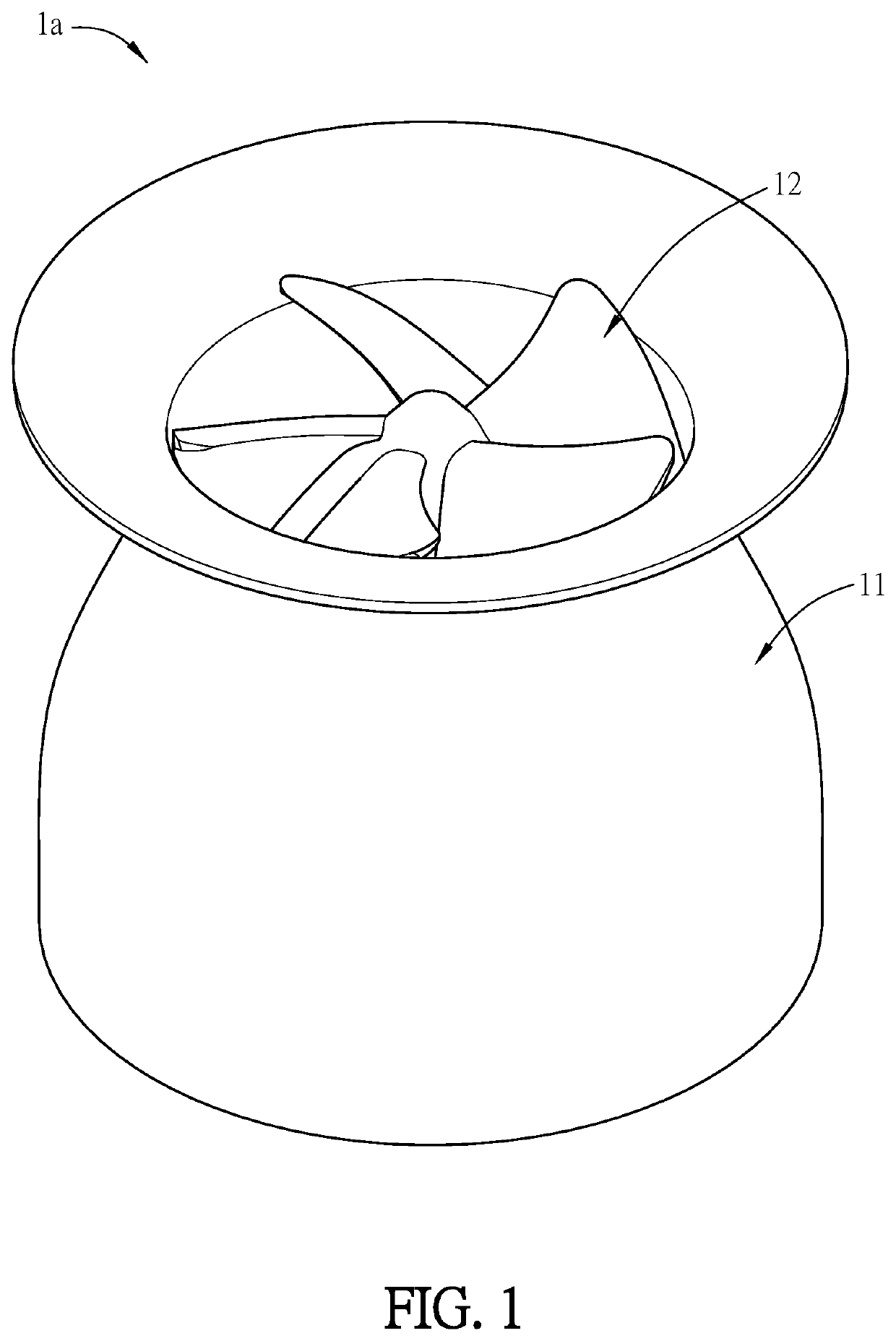
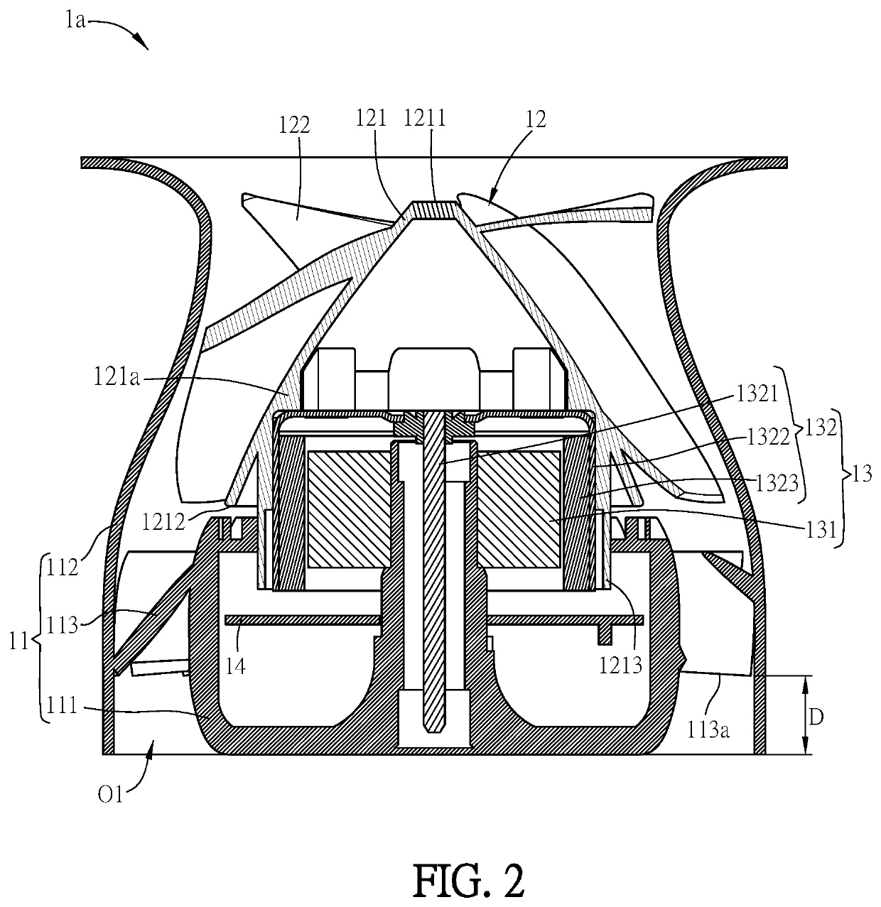
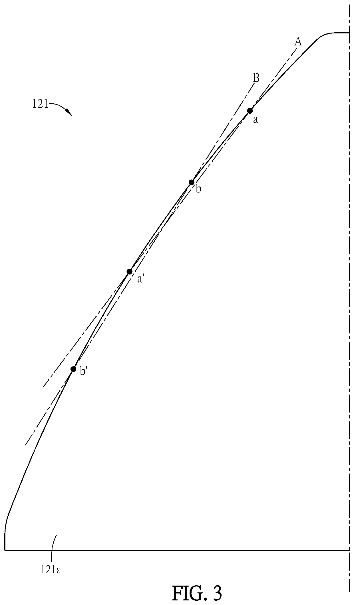
[0046]FIG. 1 is a schematic diagram showing a fan 1a according to this disclosure, and FIG. 2 is a sectional view of the fan 1a of FIG. 1. Referring to FIGS. 1 and 2, the fan 1a comprises a frame 11, an impeller 12, and a motor 13. The frame 11 comprises a base 111, a frame housing 112, and a plurality of static blades 113. The frame housing 112 comprises an outlet O1, and the static blades 113 are disposed around an outer periphery of the base 111 and connect between the base 111 and the frame housing112. A distance D is defined between the outlet O1 and the ends 113a of the static blades 113 located adjacent to the outlet O1, and the static blades 113 are not protruding from the outlet O1. In other words, the static blades 113 are sunken in the outlet O1. The impeller 12 comprises a hub 121 and a plurality of rotor blades 122. The hub 121 has a curved surface 121a, and the slopes of the straight lines connecting any two points on the curved surface 121a are not equal. The rotor bl...

second embodiment

[0049]FIGS. 4 to 6 are schematic diagrams of a fan 1b according to this disclosure. Referring to FIGS. 4 to 6, the fan 1b comprises a frame 11, an impeller 12, and a motor 13. The frame 11 comprises a base 111, a frame housing 112, and a plurality of static blades 113. The frame housing 112 comprises and inlet O2 and an outlet O1, and the static blades 113 are disposed around an outer periphery of the base 111 and connect between the base 111 and the frame housing 112. A distance D is defined between the outlet O1 and the ends 113a of the static blades 113 located adjacent to the outlet O1, and the static blades 113 are not protruding from the outlet O1. In other words, the static blades 113 are sunken in the outlet O1. The impeller 12 comprises a hub 121, a plurality of rotor blades 122, and a plurality of guiding plates 123. The hub 121 has a curved surface 121a, and the slopes of the straight lines connecting any two points on the curved surface 121a are not equal. The hub 121 ha...


PUM


Abstract

A fan includes a frame, an impeller and a motor. The frame includes a base, a frame housing and a plurality of static blades. The frame housing includes an outlet. The static blades are disposed around the outer periphery of the base and connect between the base and the frame housing. A distance is provided between the outlet and the ends of the static blades located adjacent to the outlet, and the static blades are not protruding from the outlet. The impeller includes a hub and a plurality of rotor blades. The hub has a curved surface. The slopes of the straight lines connecting any two points on the curved surface are not equal. The rotor blades are disposed around the outer periphery of the hub. The motor is disposed on the base, and connects with and drives the impeller to rotate.

Description

CROSS REFERENCE TO RELATED APPLICATIONS[0001]This Non-provisional application claims priority under 35 U.S.C. § 119(a) on Patent Application No(s). 201811281520.9 filed in People's Republic of China on Oct. 23, 2018, the entire contents of which are hereby incorporated by reference.BACKGROUND OF THE INVENTIONField of Invention[0002]This disclosure relates to a fan and, in particular, to a mixed flow fan with sunken static blades.Related Art[0003]As the performance of electronic devices continuously increases, the current electronic devices generate a large amount of waste heat during operation. If the heat cannot be immediately removed from the electronic device, the temperature of the electronic device will rise, thereby causing damage to internal components and reducing the performance and lifetime of the electronic device. Fans are the heat-dissipation devices that are widely used in electronic devices. At present, those skilled in the art have developed a fan with the blades and...

Claims


Application Information

Patent Timeline
Patent Type & Authority Applications(United States)
IPC IPC(8): F04D19/00F04D25/06F04D29/38F04D29/52
CPCF04D19/002F04D25/064F04D29/38F04D29/522F04D25/08F04D29/26F04D29/403F04D29/584F04D29/663F04D17/06F04D29/30F04D29/444
Inventor CHANG, SHUN-CHENYANG, CHAO-FU
Owner DELTA ELECTRONICS INC
Why Eureka
Try Eureka