Dynamic damper device

Inactive Publication Date: 2020-04-23
EXEDY CORP
View PDF0 Cites 3 Cited by
  • Summary
  • Abstract
  • Description
  • Claims
  • Application Information

AI Technical Summary

Benefits of technology

[0033]Overall, according to the present invention described above, installation of a stopper mechanism used so far in a well-known dynamic damper device can be abolished in the present dynamic damper device, whereby simplification in structure and compactness in size of the present dynamic damper device can be achieved. Additionally

Problems solved by technology

On the other hand, when the rotational phase difference is produced between the rotary member and the mass member, the

Method used


Image

  • Dynamic damper device
  • Dynamic damper device
  • Dynamic damper device

Examples


Embodiment Construction

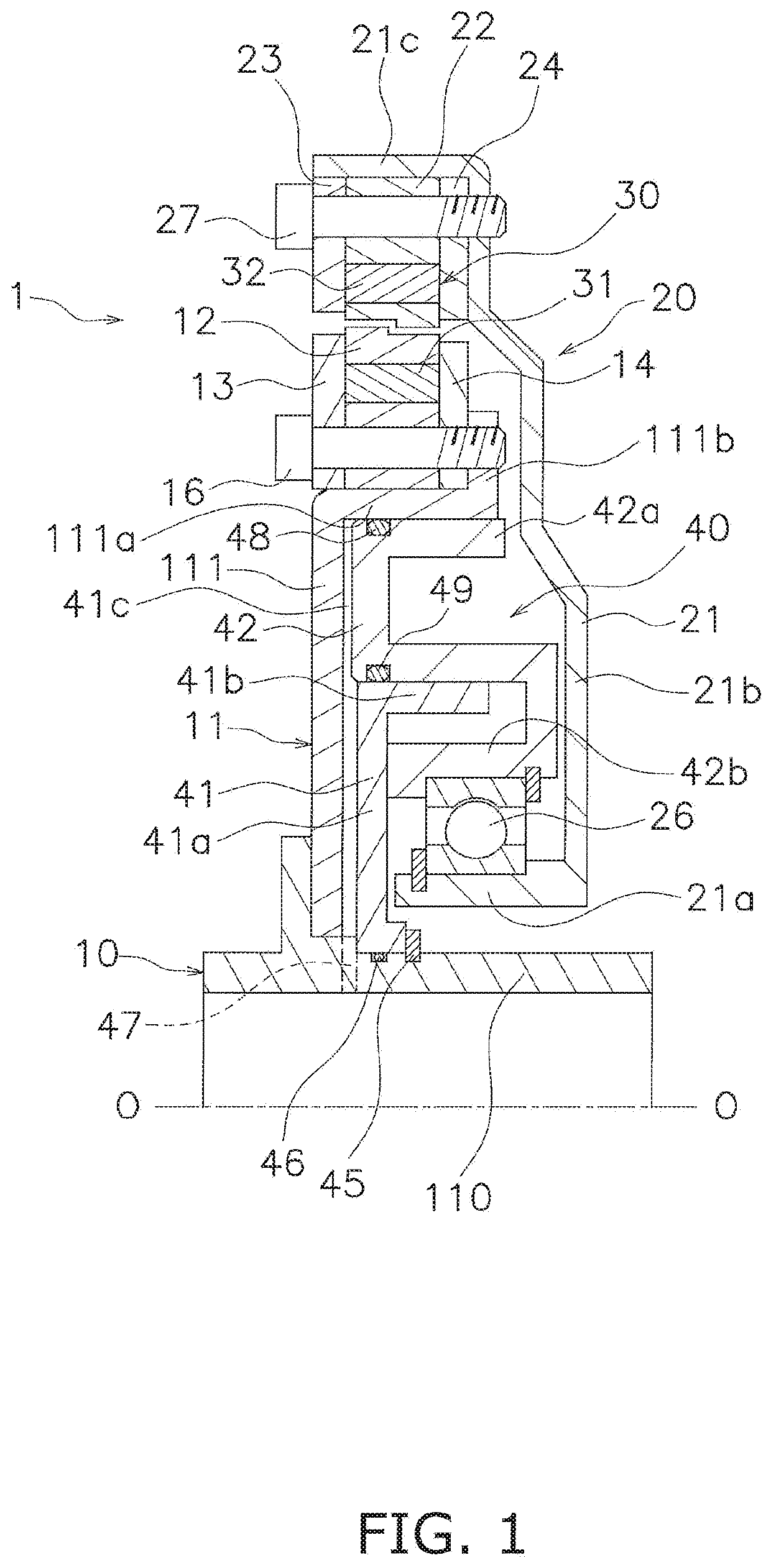
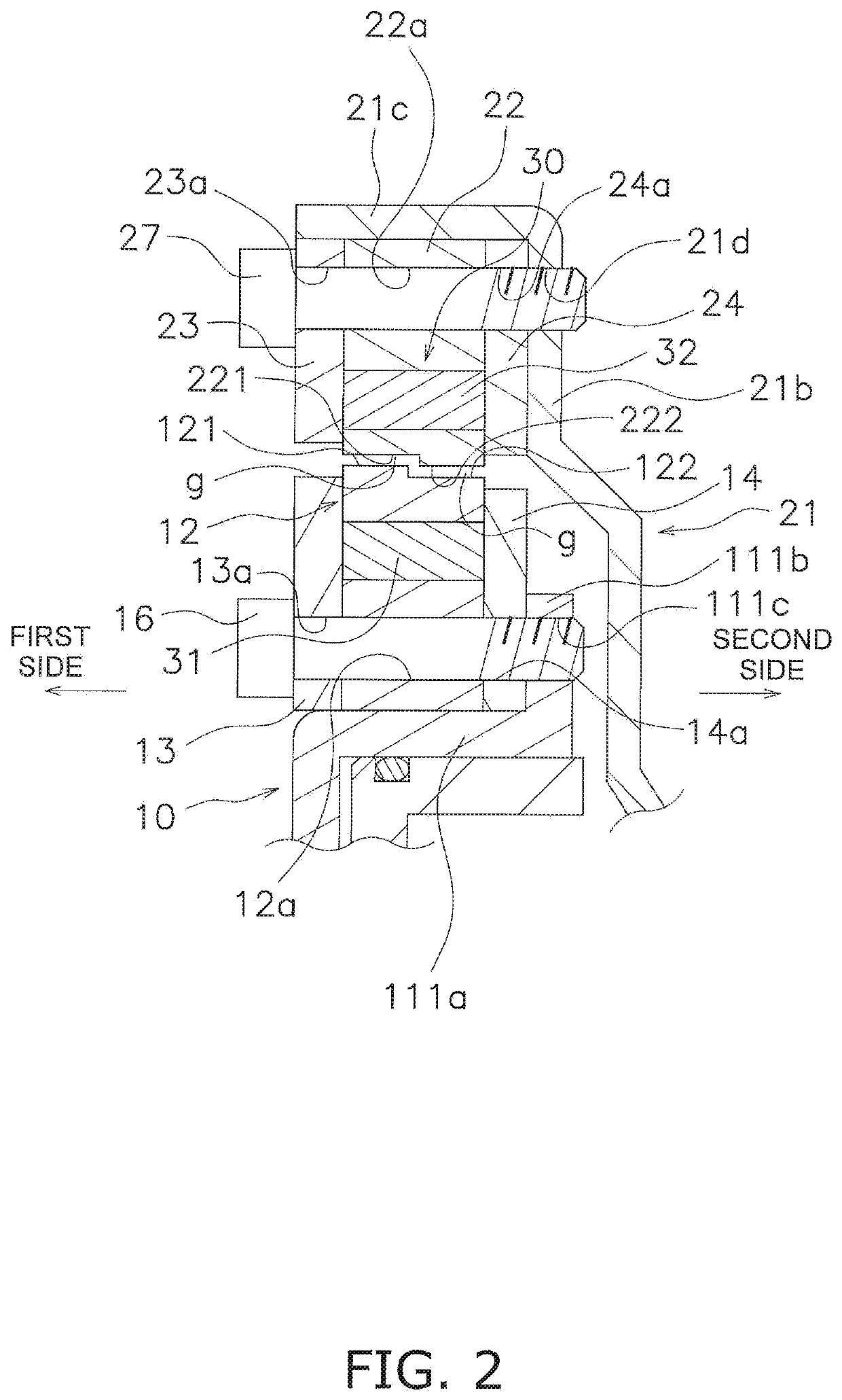
[0049]FIG. 1 is a cross-sectional view of a dynamic damper device 1 according to a preferred embodiment of the present invention. In FIG. 1, line O-O indicates a rotational axis. On the other hand, FIG. 2 is an enlarged view of the outer peripheral part of the dynamic damper device 1 shown in FIG. 1.

[0050][Entire Configuration]

[0051]The dynamic damper device 1 includes a rotary member 10 to which a torque is inputted, a mass member 20, a magnetic damper mechanism 30 and a moving mechanism 40. The rotary member 10 is provided in, for instance, a lock-up device for a torque converter. Specifically, the torque is inputted to the rotary member 10, for instance, from a front cover through a clutch part and a damper mechanism. The torque, inputted to the rotary member 10, is then transmitted to a transmission-side input shaft.

[0052][Rotary Member 10]

[0053]The rotary member 10 includes a first support plate 11, a first holder 12 and a pair of inner peripheral side plates 13 and 14.

[0054]Th...


PUM


Abstract

A dynamic damper device includes a rotary member, a mass member, and a magnetic damper mechanism. The rotary member includes a first opposed surface. The mass member is disposed to be rotatable together with the rotary member, and rotatable and axially movable relative to the rotary member. The mass member includes a second opposed surface. The second opposed surface is radially opposed at a gap to the first opposed surface. The magnetic damper mechanism includes magnets, and is configured to magnetically couple the rotary member and the mass member by the magnets. The magnetic damper mechanism is configured to generate a resilient force to reduce the relative displacement produced between the rotary member and the mass member in a rotational direction. The first and second opposed surfaces are shaped such that the gap therebetween is variable with an axial movement of either the rotary member or the mass member.

Description

CROSS-REFERENCE TO RELATED APPLICATIONS[0001]This application claims priority to Japanese Patent Application No. 2018-195675, filed Oct. 17, 2018. The contents of that application are incorporated by reference herein in their entirety.TECHNICAL FIELD[0002]The present invention relates to a dynamic damper device, particularly to a dynamic damper device for inhibiting torque fluctuations in a rotary member to which a torque is inputted.BACKGROUND ART[0003]For example, a clutch device, including a damper device, and a torque converter are provided between an engine and a transmission in an automobile. Additionally, for reduction in fuel consumption, the torque converter is provided with a lock-up device for mechanically transmitting a torque at a predetermined rotational speed or greater.[0004]In general, the lock-up device includes a clutch part and a damper including a plurality of torsion springs. In the lock-up device described above, torque fluctuations are inhibited by the damper...

Claims


Application Information

Patent Timeline
IPC IPC(8): F16F15/18
CPCF16D2300/22F16F15/18
Inventor MATSUOKA, YOSHIHIRO
Owner EXEDY CORP
Why Eureka
Try Eureka