
Methods for achieving, and apparatus having, reduced display device energy consumption

a technology of display device and energy consumption, which is applied in the field of display device, can solve the problems of reducing the time a user can utilize the electronic device, sacrificing display image quality by reducing brightness, and user frustration, so as to reduce energy consumption, maximize battery life, and low reflection characteristics

Active Publication Date: 2020-04-23
CORNING INC
View PDF0 Cites 2 Cited by
  • Summary
  • Abstract
  • Description
  • Claims
  • Application Information

AI Technical Summary

Benefits of technology

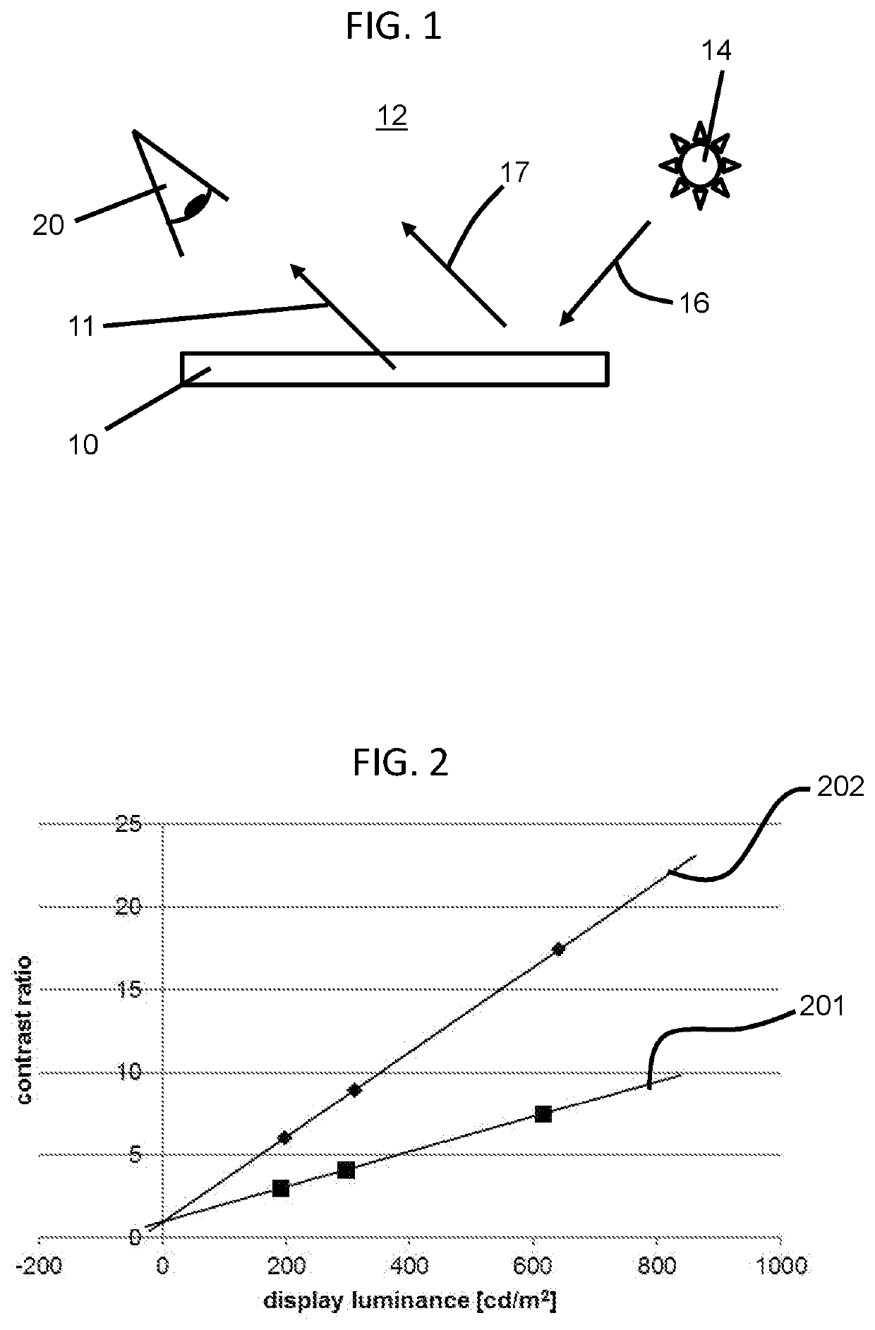
The patent describes methods and electronic devices that have a display with an anti-reflection coating that provides a better viewing experience for the user while also reducing energy consumption. The anti-reflection coating has high hardness, low reflectance, and low color shift with angle. The methods use characteristics of the ambient lighting, display reflectance, display luminance, and content type to minimize energy consumption while still delivering a good viewing experience to the user. The device controller can adjust display device conditions to match a target display quality to further reduce energy consumption. Overall, the method and device can provide a better user experience with reduced energy consumption and extended battery life.

Problems solved by technology

It is a source of user frustration when the portable energy source capacity is consumed quickly and frequent charging events are performed typically at a fixed external energy source, for example an electrical outlet in a user's home.
Further, the time taken for charging events reduces the time a user can utilize the electronic device, and / or the time the user can utilize the electronic device away from a fixed external energy source.
Although there have been methods of reducing display brightness to reduce energy consumption, such methods sacrifice display image quality by reducing brightness.
Yet users typically do not want to sacrifice display image quality or device functionality in order to prolong energy source life.
However, these devices, even the ones which have included anti-reflection coatings, have not functioned so as to maintain the user's perceived display image quality under varying ambient lighting conditions, while also maximizing the battery life and / or minimizing the energy consumption of the display device.
That is, if the anti-reflection coating is scratched or otherwise damaged, the viewing experience is degraded, and the reflectance thereof may be increased thereby reducing the effectiveness of the techniques of the present disclosure to reduce energy consumption.

Method used


Image

  • Methods for achieving, and apparatus having, reduced display device energy consumption
  • Methods for achieving, and apparatus having, reduced display device energy consumption
  • Methods for achieving, and apparatus having, reduced display device energy consumption

Examples


example 1

[0091]The as-fabricated samples of Example 1 (“Ex. 1”) were formed by providing a glass substrate having a nominal composition of 67 mol % SiO2, 4 mol % B2O3, 13 mol % Al2O3, 14 mol % Na2O, and 2 mol % MgO and disposing an anti-reflective coating having thirteen (13) layers on the glass substrate as shown in Table 1 below. The anti-reflective coating (e.g., as consistent with the anti-reflective coatings outlined in the disclosure) of each of the as-fabricated samples in this Example was deposited using a reactive sputtering process.

TABLE 1Anti-reflective coating attributes for Example 1RefractiveEx. 1MaterialIndexThickness (nm)LayerAir1.01SiO21.4890.52SixNy2.05150.23SiO21.4816.64SixNy2.0546.35SiO21.4896SixNy2.0520007SiO21.4810.98SixNy2.0537.39SiO21.483310 SixNy2.0523.411 SiO21.485312 SixNy2.057.613 SiO21.4825Glass substrate1.51Total thickness2502.8Reflected colorY0.7L*a*b*Hardness (GPa)@ 100 nm depth12@ 500 nm depthMax hardnessHmax (GPa)18Depth (nm)900Film stress(MPa)Surface(nm)rou...

example 2

[0092]The as-fabricated samples of Example 2 (“Ex. 2”) were formed by providing a glass substrate having a nominal composition of 67 mol % SiO2, 4 mol % B2O3, 13 mol % Al2O3, 14 mol % Na2O, and 2 mol % MgO and disposing an anti-reflective coating having thirteen (13) layers on the glass substrate as shown in Table 2 below. The anti-reflective coating (e.g., as consistent with the anti-reflective coatings outlined in the disclosure) of each of the as-fabricated samples in this Example was deposited using a reactive sputtering process.

TABLE 2Anti-reflective coating attributes for Example 2RefractiveEx. 2MaterialIndexThickness (nm)LayerAir1.01SiO21.4890.32SixNy2.05154.63SiO21.4819.84SixNy2.05535SiO21.4812.36SixNy2.055007SiO21.4811.68SixNy2.0542.69SiO21.4837.510 SixNy2.0522.911 SiO21.4862.312 SixNy2.058.413 SiO21.4825Glass substrate1.51Total thickness1040.3Reflected colorY0.75L*a*−1.14b*−0.98Hardness (GPa)@ 100 nm depth10@ 500 nm depthMax hardnessHmax (GPa)14(from 100 nm toDepth (nm)450...

example 3

[0093]The as-fabricated samples of Example 3 (“Ex. 3”) were formed by providing a glass substrate having a nominal composition of 69 mol % SiO2, 10 mol % Al2O3, 15 mol % Na2O, and 5 mol % MgO and disposing an anti-reflective coating having five (5) layers on the glass substrate as shown in Table 3 below. The anti-reflective coating (e.g., as consistent with the anti-reflective coatings outlined in the disclosure) of each of the as-fabricated samples in this Example was deposited using a reactive sputtering process.

[0094]The modeled samples of Example 3 (“Ex. 3-M”) were assumed to employ a glass substrate having the same composition of the glass substrate employed in the as-fabricated samples of this example. Further, the anti-reflective coating of each of the modeled samples was assumed to have the layer materials and physical thickness as shown in Table 3 below.

TABLE 3Anti-reflective coating attributes for Example 3RefractiveEx. 3-MEx. 3MaterialIndexThickness (nm)LayerAir1.01SiO21....


PUM


Abstract

A method, of reducing display device energy consumption, including: (a) determining lighting conditions ambient to a display device; (b) determining content that a user chooses to view on the display device; (c) calculating the user's perception of display quality using an image appearance model; and (d) adjusting, when the perceived display quality is higher than a target display quality, display device conditions so that the perceived display quality matches the target display quality so as to reduce energy consumption. An apparatus utilizing the method so as to reduce energy consumption while providing an aesthetically pleasing viewing experience to a user.

Description

BACKGROUNDField[0001]This application claims the benefit of priority under 35 U.S.C. § 119 of U.S. Provisional Application Ser. No. 62 / 746,811, filed on Oct. 17, 2018, the content of which is relied upon and incorporated herein by reference in its entirety.[0002]The present disclosure relates generally to display devices and, more particularly, to methods for achieving, and display devices having, reduced energy consumption.Technical Background[0003]Electronic devices, for example, smartphones, smart watches, tablets, and laptop computers, have display devices that consume energy. Typically, these display devices will run on a portable energy source, for example a battery. It is a source of user frustration when the portable energy source capacity is consumed quickly and frequent charging events are performed typically at a fixed external energy source, for example an electrical outlet in a user's home. Further, the time taken for charging events reduces the time a user can utilize ...

Claims


Application Information

Patent Timeline
Patent Type & Authority Applications(United States)
IPC IPC(8): G09G5/10G09G5/02
CPCG09G2320/0666G09G5/10G09G2354/00G09G2360/144G09G2320/0626G09G5/02G09G2330/023G09G2330/021G09G2320/066G09G5/003G09G2320/0233G09G3/2092G09G2320/0271G09G2320/0613G09G2320/08
Inventor AMIN, JAYMINHART, SHANDON DEEHATHAWAY, BROOKE AMBERKOCH, III, KARL WILLIAMKOSIK WILLIAMS, CARLO ANTHONYMAYOLET, ALEXANDRE MICHEL
Owner CORNING INC
Learn More