Fuel cell separator, method for producing the same, and apparatus for producing the same

Active Publication Date: 2020-04-23
TOYOTA JIDOSHA KK
View PDF0 Cites 0 Cited by
  • Summary
  • Abstract
  • Description
  • Claims
  • Application Information

AI Technical Summary

Benefits of technology

[0013]In the apparatus for producing the fuel cell separator according to the present disclosure, since the die has the facing surface that is adapted to face one surface of the separator substrate and the projections that project from the facing surface toward the separator substrate and are adapted to form the grooves, the grooves can easily be formed on the separator substrate.
[0014]In some embodiments of the apparatus for producing the fuel cell separator according to the present disclosure, provided that the height of each projection projecting from the facing surface is represented as A, the depth of each groove of the fuel cell separator to be produce

Problems solved by technology

The fuel cell devices with such a structure have a problem in that a reactant gas cannot easily enter portions where the projections (more specifically,

Method used


Image

  • Fuel cell separator, method for producing the same, and apparatus for producing the same
  • Fuel cell separator, method for producing the same, and apparatus for producing the same
  • Fuel cell separator, method for producing the same, and apparatus for producing the same

Examples


Example

[0025]Embodiments of a fuel cell separator according to the present disclosure and a method and apparatus for producing the same will be described below with reference to the drawings.

[Fuel Cell Separator]

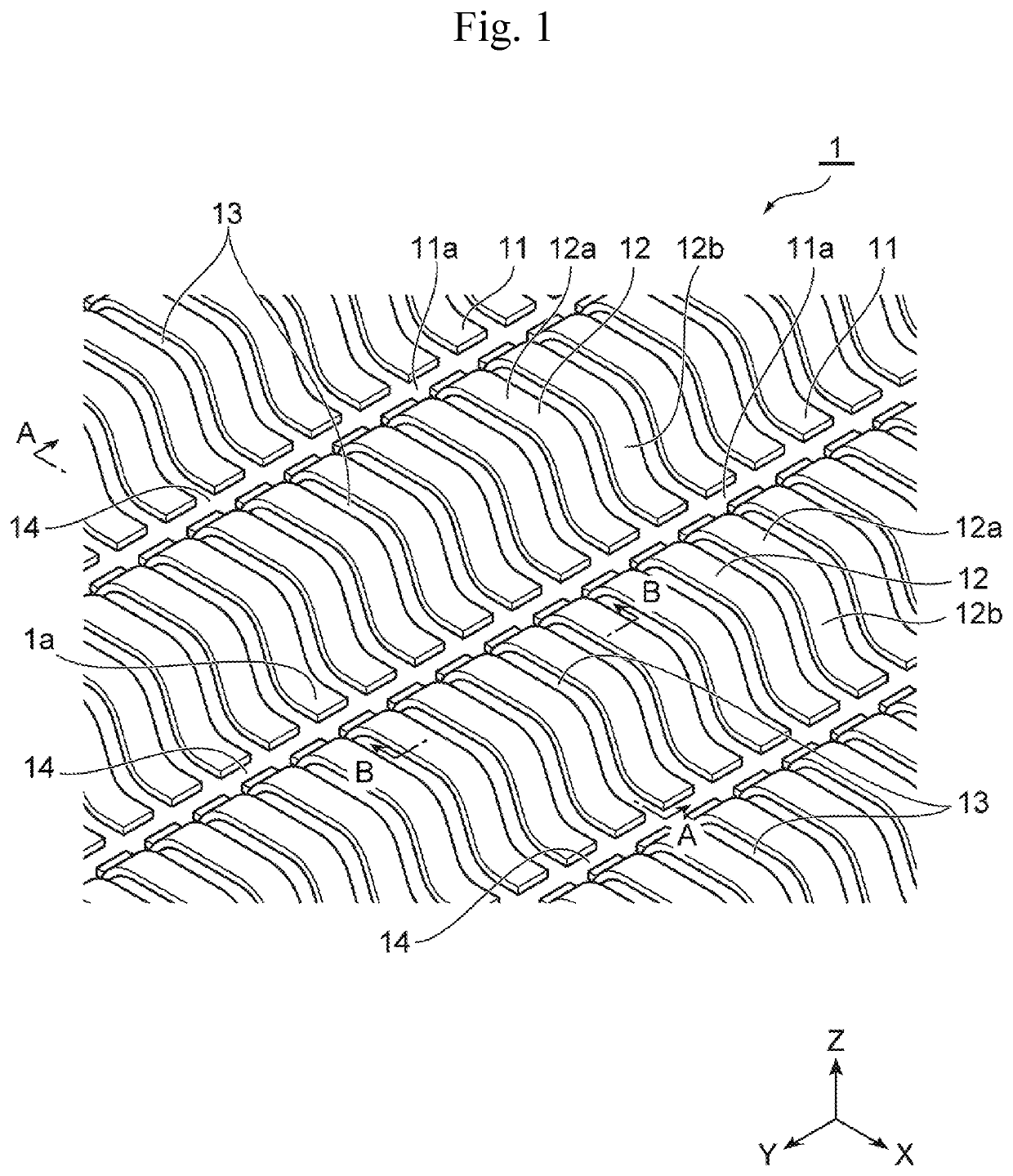
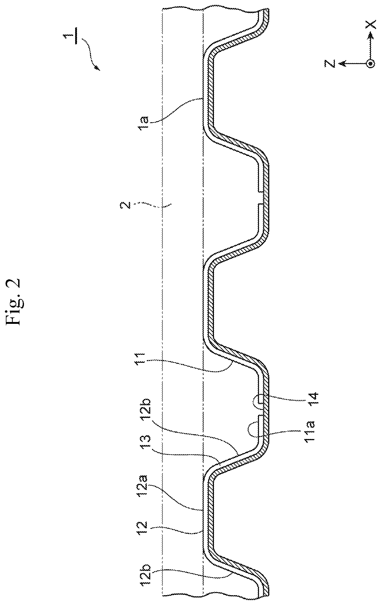
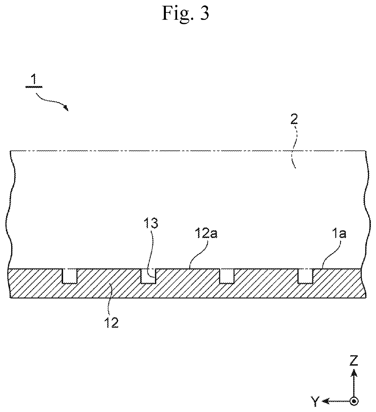
[0026]FIG. 1 is a partial perspective view of a fuel cell separator according to an embodiment, FIG. 2 is a cross-sectional view of the fuel cell separator taken along line A-A of FIG. 1, and FIG. 3 is a cross-sectional view of the fuel cell separator taken along line B-B of FIG. 1. In the drawings, the width direction, longitudinal direction, and thickness direction (also referred to as the up-down direction) of the fuel cell separator are represented as a first direction X, a second direction Y, and a third direction Z, respectively. Further, in FIG. 2 and FIG. 3, for easy understanding of the positional relation between the fuel cell separator and a membrane electrode assembly, the membrane electrode assembly is also shown (see a portion depicted with a two-dot chain line) for r...


PUM


Abstract

A fuel cell separator capable of surely discharging produced water, and a method and apparatus for producing the same. The fuel cell separator is formed in a wave shape with recesses and projections alternately arranged in a first direction, the recesses forming reactant gas channels together with a membrane electrode assembly and the projections abutting the membrane electrode assembly, in which on a surface of the fuel cell separator that is adapted to face the membrane electrode assembly, a plurality of first grooves extending in the first direction along the corrugation of the recesses and projections is disposed at intervals from each other in a second direction orthogonal to the first direction, and a second groove extending in the second direction and communicating with the plurality of first grooves is disposed in the bottom portion of each recess.

Description

CROSS REFERENCE TO RELATED APPLICATIONS[0001]The present application claims priority from Japanese patent application JP 2018-196508 filed on Oct. 18, 2018, the content of which is hereby incorporated by reference into this application.BACKGROUNDTechnical Field[0002]The present disclosure relates to a fuel cell separator, a method for producing the same, and an apparatus for producing the same.Background Art[0003]Fuel cell devices are formed by stacking a plurality of fuel cells and generate power through electrochemical reactions of supplied reactant gases (that is, an oxidant gas and a fuel gas). A fuel cell that has been known includes a membrane electrode assembly, which includes an electrolyte membrane and a pair of electrodes sandwiching the electrolyte membrane, and a pair of fuel cell separators sandwiching the membrane electrode assembly. The fuel cell separators are each formed in a wave shape with recesses and projections alternately arranged, the recesses forming reactan...

Claims


Application Information

Patent Timeline
IPC IPC(8): H01M8/026H01M8/0223H01M8/0254H01M8/1004
CPCH01M8/026H01M8/0254H01M8/1004H01M2008/1095H01M8/0223H01M8/0202H01M8/0263H01M8/1006Y02E60/50Y02P70/50
Inventor NOBATA, YASUHIRO
Owner TOYOTA JIDOSHA KK
Why Eureka
Try Eureka