A mouthpiece and heater assembly for an inhalation device

a technology of inhalation device and heater assembly, which is applied in the direction of ohmic-resistance waterproof/air-tight seals, tobacco, other medical devices, etc., can solve the problems of increasing the thermal mass of the wick, unnecessarily wasting heat generated by the coil (b>5/b>) in heating all of the e-liquid, and reducing the energy efficiency of the device. , to achieve the effect of faster travel

Active Publication Date: 2020-04-30
VENTUS MEDICAL LTD
View PDF0 Cites 3 Cited by
  • Summary
  • Abstract
  • Description
  • Claims
  • Application Information

AI Technical Summary

Benefits of technology

[0059]The airflow channel may include a constriction orifice for restricting the flow of air therewithin. Employing a constriction orifice within the airflow channel results in a pressure drop within the airflow channel and may permit the velocity of the airflow to be controlled more accurately (e.g. by the Venturi effect) in the region of the constriction orifice allowing airflow over the heater to travel faster compared to the ai...

Problems solved by technology

This increases the thermal mass of the wick (3) and means that the heat generated by the coil (5) is unnecessarily expended in heating all of the e-liquid rather than the amount that actually needs to be vaporized.
Heating surplus liquid reduces the energy efficiency of the device.
This reduces heat transfer to the wick and means that the coil (5) has to be excessively powered to compensate for the radiative dissipation of heat from the coil and inefficiencies of heating a large substrate and volume of liquid.
This again reduces the energy efficiency of the device.
Moreover, surplus e-liquid and repeated heating to a higher temperature increases the risk that a user will receive a larger dose of nicotine than intended and increases the potential for degradation of both nicotine and excipients.
Another problem with known e-cigarette heaters is that their design does not lend itself to automation.
A further problem with known e-cigarettes is that a user can refill their device with e-liquids which are not intended for that device and consequently may have higher levels of nicotine or additives which undergo an adverse reaction upon ...

Method used


Image

  • A mouthpiece and heater assembly for an inhalation device
  • A mouthpiece and heater assembly for an inhalation device
  • A mouthpiece and heater assembly for an inhalation device

Examples


Embodiment Construction

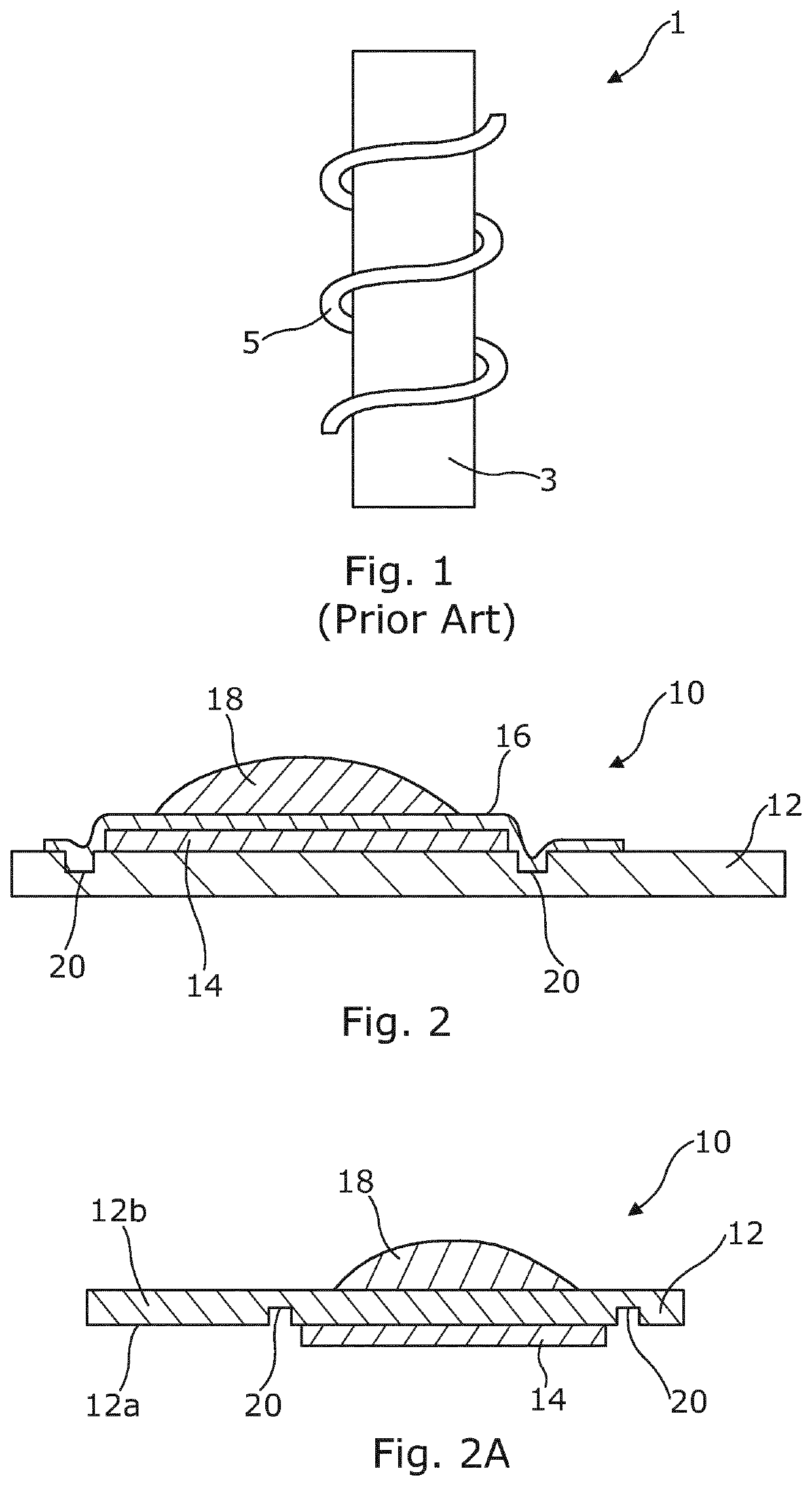
[0081]FIG. 2 shows a heater 10 for an inhalation device according to the present invention comprising a substrate 12 and a resistive heating element 14, which is supported by a portion of the substrate 12. The resistive element portion is connectable to an electric power source (not shown) by means of contacts (not shown). A barrier layer 16 overlies the resistive element portion 14 and part of the substrate 12. The heater 10 is shown with an amount of composition 18 which has been deposited on the barrier layer 16.

[0082]When an electric current flows through resistive element portion 14 the temperature of the resistive element portion 14 increases and heat is transferred through the barrier layer 16 to the composition 18. At least a portion of the composition 18 vaporizes and is dispersed into the air above the heater 10. As the composition 18 evaporates away from the heater it cools and some of the vaporized composition condenses to form liquid droplets of composition suspended in...


PUM


Abstract

An inhalation device includes a mouthpiece and a heater having a rigid planar substrate which supports at least one resistive element portion applied over a first region of at least one surface of the substrate, and a pair of contacts each connected to the at least one resistive element portion at one end of the contacts and applied over a second region of the at least one surface of the substrate. The substrate supports an aerosolizable composition deposited on the substrate above the resistive element portion of the heater. The mouthpiece has at least a fluid inlet and a fluid outlet proximate rear and front ends thereof respectively. The heater is disposed within the mouthpiece with at least portions of the contacts being both exposed and accessible so that an electrical connection can be readily achieved when the rear end of the mouthpiece is connected to the inhalation device.

Description

CROSS-REFERENCE TO RELATED APPLICATION[0001]This application is a 371 of International Application No. PCT / EP2018 / 056429, filed on Mar. 14, 2018, which is incorporated by reference in its entirety.TECHNICAL FIELD[0002]The present invention relates to a mouthpiece and heater assembly for an inhalation device. The heater is configured to heat a composition to generate an aerosol for inhalation by a user. In particular, but not exclusively, the present invention relates to a heater for a nicotine replacement therapy or a smoking-substitute device. Furthermore, the present invention relates to a mouthpiece comprising the heater, an inhalation device comprising the heater and a method of manufacturing the heater.[0003]Although the present application will focus on heating compositions containing nicotine for inhalation by user, it will be appreciated that the heater can be used for heating compositions comprising other compounds, for example, medicaments or flavorings.BACKGROUND[0004]Nic...

Claims


Application Information

Patent Timeline
IPC IPC(8): A24F40/46A24F40/10
CPCA24F40/46A24F40/10A61M15/0021A61M15/06A61M2205/8206H05B3/10H05B3/20H05B3/04A24F47/00
Inventor CANE, MICHAELHART, OLIVERDIGNUM, MARKLAWSON, DAVID
Owner VENTUS MEDICAL LTD
Why Eureka
Try Eureka