A valve position sensor

a position sensor and valve technology, applied in the direction of instruments, liquid/fluent solid measurement, transportation and packaging, etc., can solve the problem of fluctuation of estimated angl

Active Publication Date: 2020-04-30
SENTEC AS
View PDF0 Cites 6 Cited by
  • Summary
  • Abstract
  • Description
  • Claims
  • Application Information

AI Technical Summary

Benefits of technology

[0048]The valve position sensor may optionally include a permanent magnet, fixed to a stationary part of the valve. In this way, a strong well defined local magnetic field in the vicinity of the valve is provided such that, any inaccuracy in angle estimation due to a varying local magnetic field or magnetic moving valve part is minimised.

Problems solved by technology

This is in contrast to, for example, using purely gyroscopic data where long term drift and bit resolution of the gyroscope zero offset will give rise to integration errors, leading to fluctuations in estimated angle.

Method used


Image

  • A valve position sensor
  • A valve position sensor
  • A valve position sensor

Examples


Embodiment Construction

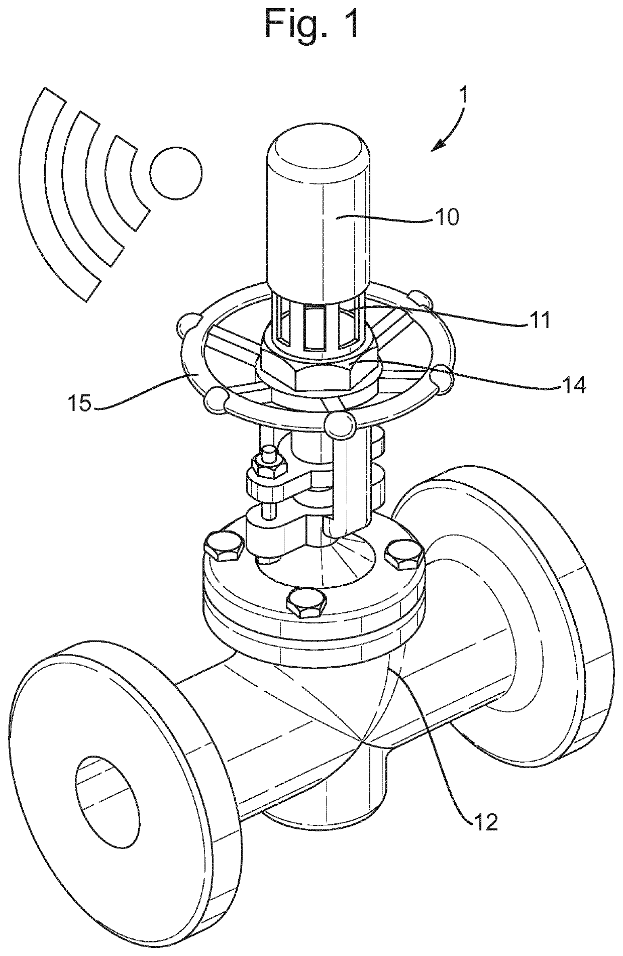
[0057]FIG. 1 schematically illustrates a valve position sensor 1 according to the present invention. The valve position sensor 1 comprises a sensor housing 10 for placement on an outside of a moveable part of a valve 12 and, within the sensor housing 10, a print circuit board assembly comprising one or more microsensors, the one or more microsensors including a magnetometer. The valve position sensor further comprises a processing unit configured to receive data from the magnetometer and compare the received magnetometer data with predetermined calibration data to determine a position of the valve 12 based on the orientation of the magnetometer relative to the surrounding magnetic field. The sensor also includes a transmitter for wirelessly transmitting event data including valve position data to an external receiver.

[0058]In the example of FIG. 1 the valve position sensor 1 includes a fixation base 11 which takes the form of a partially hollow cylindrical cap which is configured to...


PUM


Abstract

A valve position sensor (1) is described. The valve position sensor comprises a sensor housing (10) for placement on a moving component of a valve (12); a print circuit board assembly disposed within the housing, the print circuit board assembly comprising: one or more micro sensors, the one or more micro sensors including a magnetometer; a processing unit configured to receive data from the magnetometer and compare the received magnetometer data with predetermined calibration data to determine valve position data relating to an estimate of the valve position; and a transmitter for wirelessly transmitting event data including valve position data to an external receiver. The valve position sensor provides a low cost means to remotely determine the position of a valve.

Description

TECHNICAL FIELD[0001]The present invention relates to a valve position sensor, and a method for monitoring and determining the valve position of a valve.BACKGROUND[0002]Manual and automated valves are installed in vast quantities in many different types of processing plants. Large quantities are installed in the oil and gas industry, pulp & paper, chemical, pharmaceutical and similar processing plants.[0003]In many such applications it is important to know the valve positions of the valves within a system in order to ensure the correct functioning of the system and to ensure safety. The need to determine and record the positions of the valves in a system is vital for both optimum process control during operation but also for maintenance, for example when a system must be safely shut down or particular components isolated.[0004]In known systems, generally only control valves with a cabled connection to the control panel or operating system allows for direct reporting to the operator ...

Claims


Application Information

Patent Timeline
Patent Type & Authority Applications(United States)
IPC IPC(8): F16K37/00G01D5/12G01D18/00
CPCF16K37/0033G01D5/12G01D18/008F16K37/0041G01R33/028G01R35/00F16K37/0083Y10T137/8275Y10T137/8158
Inventor GISMERVIK, ØYSTEINKARLSEN, RONNYSANDØ, JØM R.
Owner SENTEC AS
Why Eureka
Try Eureka