Method for operating a charging device

a charging device and charging circuit technology, applied in the direction of battery data exchange, exchanging data chargers, transportation and packaging, etc., can solve the problems of excessively high charging voltage, damage to electrical energy stores, and limited power drawn from the power supply system for charging, so as to achieve reliable charging operation, cost advantage, energy efficiency

Active Publication Date: 2020-04-30
ROBERT BOSCH GMBH
View PDF0 Cites 0 Cited by
  • Summary
  • Abstract
  • Description
  • Claims
  • Application Information

AI Technical Summary

Benefits of technology

[0005]The method according to the invention has the advantage that, in order to charge an electrical energy store, charging durations for the quickest charging and for relatively slow charging operations with less heating of the components taking into consideration the families of efficiency characteristics of the charging device and / or the electrical energy store are output on an interface.
[0007]Advantageously, the charging device communicates with a server and requests the present electricity tariff. It is of great advantage that, by taking into consideration the present electricity tariff and the use of the energy-efficient extended charging durations with improved overall efficiency, the costs for the charging operation are minimized. Secondly, advantageously a very low electricity tariff can be used for quick charging of the electrical energy store when the low electricity costs eliminate the disadvantage of the relatively high energy demand owing to the relatively poor efficiency and the energy consumption of the auxiliaries of the cooling circuit.

Problems solved by technology

If the performance capability of the power supply system is less than the performance capability of the charging device, the power drawn from the power supply system for charging is limited in such a way that no damage occurs on the power supply system or the protective devices do not respond and interrupt the charging operation.
Charging with an excessively high charging current or an excessively high charging voltage would destroy the electrical energy store.
The charging of electrical energy stores disadvantageously takes place in such a way that the respective combination of charging device and electrical energy store results in an energy transfer with the highest possible energy.
The disadvantage with this is that no consideration is given to the families of efficiency characteristics of the components involved in the charging method by the implemented IU charging method and therefore increased heating of the charging device and electrical energy store is disadvantageously accepted.
This means that, for example in the case of charging devices for electrical energy stores for electrically operated road vehicles and industrial trucks, disadvantageously complex devices for cooling the components need to be provided.
The corresponding energy stores likewise disadvantageously need to be thermally monitored and cooled, which is complex.
In the standard SAE J 1772, this disadvantage results, for example, in forced ventilation of buildings being required during charging of electrical energy stores of electrically driven vehicles.
Failure of the forced ventilation would result in a termination of the charging operation.
In addition, the heating during charging disadvantageously results in accelerated ageing of the charging device and of the electrical energy store.

Method used


Image

  • Method for operating a charging device
  • Method for operating a charging device
  • Method for operating a charging device

Examples


Embodiment Construction

[0019]All of the figures are merely schematic illustrations of the method according to the invention or parts thereof in accordance with exemplary embodiments of the invention. In particular, distances and size relationships are not reproduced true to scale in the figures. Corresponding elements have been provided with the same reference numerals in the various figures.

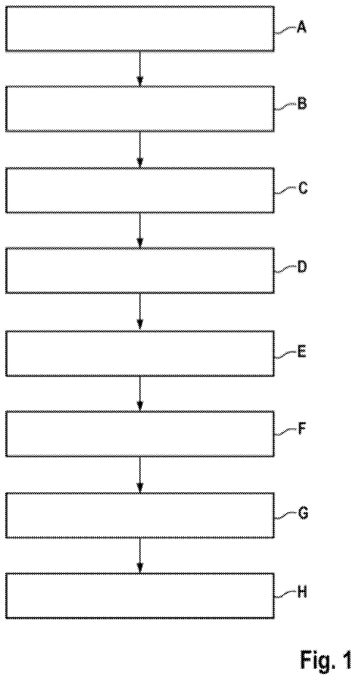
[0020]FIG. 1 shows a schematic illustration of the method according to the invention for charging an electrical energy store 20. In a first method step A, the charging device 10 communicates with the electrical energy store 20 and determines the first state of charge 22 thereof. In the subsequent second method step B, the charging device 10 determines the first family of efficiency characteristics 40 of the electrical energy store 20. In a third method step C, the charging device 10 determines a second family of efficiency characteristics 41 of the charging device 10. In a fourth method step D, the charging device 10 ...


PUM

PropertyMeasurementUnit
electrical energyaaaaaaaaaa
timeaaaaaaaaaa
voltageaaaaaaaaaa

Abstract

The invention relates to a method for operating a charging device for charging an electric energy storage device from a first charge state to a second charge state. The first charge state is lower than the second charge state, and the charging device is connected to an interface. The charging device communicates with the energy storage device and ascertains the charge state thereof. In an additional step, the charging device obtains the efficiency characteristic field of the electric energy storage device and the efficiency characteristic field of the charging device. The invention relates to a method for operating a charging device for charging an electric energy storage device from a first charge state to a second charge state. The first charge state is lower than the second charge state, and the charging device is connected to an interface. The charging device communicates with the energy storage device and ascertains the charge state thereof. In an additional step, the charging device obtains the efficiency characteristic field of the electric energy storage device and the efficiency characteristic field of the charging device.

Description

BACKGROUND OF THE INVENTION[0001]The present invention relates to a method for operating a charging device.[0002]Charging devices are used for charging electrical energy stores in order to convert the alternating current from the power supply system into direct current with a voltage matched for charging. Charging devices are likewise used in order to charge, for example, electrical energy stores from DC power supply systems when the voltage of the DC power supply system needs to be matched for charging electrical energy stores. In the case of charging devices for charging electrical energy stores such as, for example, rechargeable batteries or storage capacitors, conventionally the so-called IU method is used. By virtue of this method, the electrical energy stores are charged with a constant voltage or with a constant current. The maximum current intensity and the maximum voltage are selected depending on the requirements of the electrical energy store, and the available performanc...

Claims


Application Information

Patent Timeline
Patent Type & Authority Applications(United States)
IPC IPC(8): H02J7/00
CPCH02J7/00041H02J7/00036H02J7/00047H02J7/007H02J7/04
Inventor DITTMER, BERNDJANBEIN, TALEBFEUERSTACK, PETEREPPLER, STEFFEN
Owner ROBERT BOSCH GMBH
Why Eureka
Try Eureka