
Dynamic best path determination for penetration testing

Active Publication Date: 2020-05-07
RAPID7
View PDF0 Cites 6 Cited by
  • Summary
  • Abstract
  • Description
  • Claims
  • Application Information

AI Technical Summary

Benefits of technology

The patent describes a system for performing penetration tests to identify vulnerabilities in computer networks. The system uses a set of potential exploit actions to test the vulnerabilities. The system identifies the most efficient path through which to perform these exploits based on their risk of detection during the test. The system also schedules the performance of the next action path based on the results of the previous test. This helps to improve the efficiency and accuracy of the penetration test.

Problems solved by technology

The red team faces the trade-off of successfully achieving one or more goals (e.g., steps) of a penetration test with the risk of being discovered by the blue team (e.g., while performing exploit actions necessary to achieve said penetration testing goals).
Unfortunately, human penetration testers typically place a greater value on not being detected by the blue team versus successfully progressing in a penetration test.
Therefore, tasking human beings with making optimal risk versus reward decisions in penetration testing is undesirable.

Method used


Image

  • Dynamic best path determination for penetration testing
  • Dynamic best path determination for penetration testing
  • Dynamic best path determination for penetration testing

Examples


example kill

Chain Manager and Action Path Manager

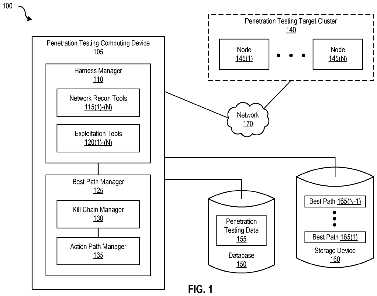
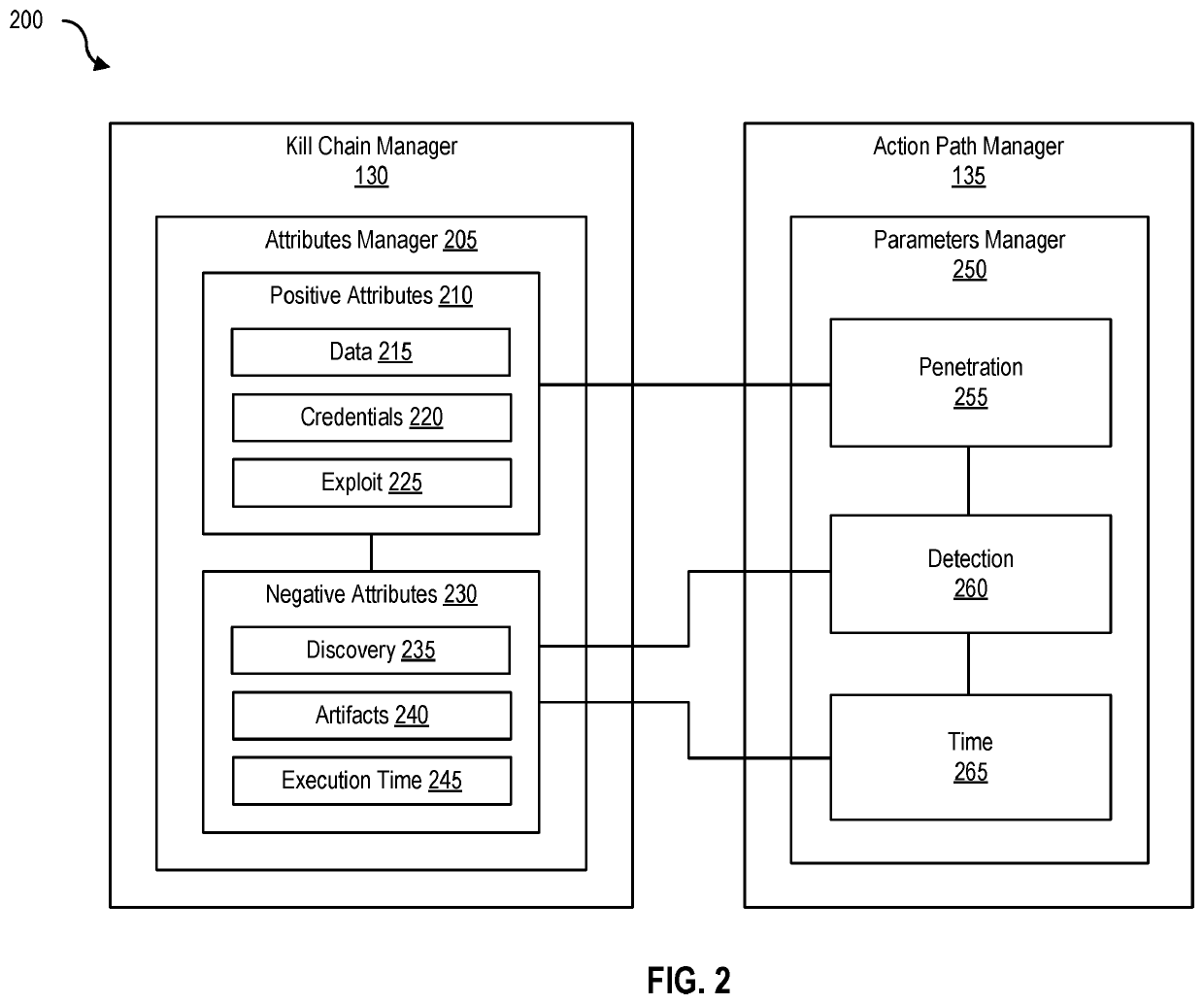
[0040]FIG. 2 is a block diagram 200 of a kill chain manager and an action path manager, according to one embodiment. Kill chain manager 130 includes at least an attributes manager 205. Attributes manager 205 includes at least one or more positive attributes 210 and one or more negative attributes 230. Examples of positive attributes include data 215 (e.g., exfiltration), credentials 220 (e.g., passwords), and exploit 225 (e.g., malicious actions), and examples of negative attributes include discovery 235 (e.g., detection), artifacts 240, and execution time 245. Action path manager 135 includes at least a parameters manager 250 that further includes at least the following parameters—penetration 255, detection 260, and time 265.

[0041]Kill chain manager 130 and action path manager 135 can be used by penetration testing computing device 105 to determine a “best path” penetration test against a given network environment (e.g., penetration testing targ...

example best

Path Determination Table

[0058]FIG. 4 is a table 400 (e.g., a best path determination table 405) that can be used by a penetration testing server to determine a best path for penetration testing, according to one embodiment. As shown in FIG. 4, a best path determination table 405 includes at least a penetration test field 410, a penetration test goal field 415, a penetration parameter field 420, a detection parameter field 425, a time parameter field 430, a kill chain field 435, and a best path field 440. Best path determination table 405 can be used by penetration testing server 305 to dynamically determine a best path for penetration testing.

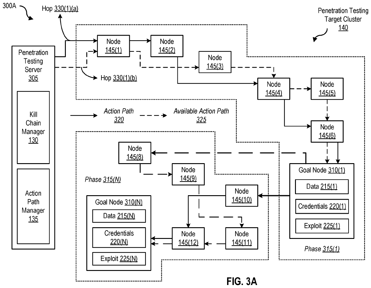
[0059]In one embodiment, penetration test 445(1) has a goal of exfiltrating data from node 145(8) (e.g., as shown in FIG. 3A). The penetration parameter (e.g., penetration 255) with the corresponding positive attribute is data 215 and the detection parameter (e.g., detection 260) with the corresponding negative attribute is discovery 235. In th...

example networking

Environment

[0084]FIG. 9 is a block diagram of a networked system, illustrating how various computing devices can communicate via a network, according to one embodiment. Network 170 generally represents any type or form of computer network or architecture capable of facilitating communication between penetration testing computing devices 105(1)-(N), penetration testing target cluster 140, and / or best path system 905. For example, network 170 can be a Wide Area Network (WAN) (e.g., the Internet) or a Local Area Network (LAN).

[0085]In certain embodiments, a communication interface, such as communication interface 845 in FIG. 8, may be used to provide connectivity between penetration testing computing devices 105(1)-(N), penetration testing target cluster 140, and / or best path system 905, and network 170. The embodiments described and / or illustrated herein are not limited to the Internet or any particular network-based environment.

[0086]In some embodiments, best path system 905 may be p...


PUM


Abstract

Disclosed herein are methods, systems, and processes to facilitate and perform dynamic best path determination for penetration testing. An action path that includes a kill chain that involves performance of exploit actions for a phase of a penetration test is generated by identifying the exploit actions based on a penetration parameter, a detection parameter, and / or a time parameter associated with the exploit actions. Performance of the identified exploit actions permits successful completion of the phase of the penetration test and designates the action path for inclusion as part of a best path for the penetration test.

Description

BACKGROUNDField of the Disclosure[0001]This disclosure is related to computer and network security. In particular, this disclosure is related to dynamic best path determination for penetration testing.Description of the Related Art[0002]Penetration testing involves an authorized simulated attack on a computer system to evaluate the security of the computer system. For example, penetration testing can identify security vulnerabilities, including the ability of potentially malicious actors to gain access to the computer system and / or associated storage devices and / or network infrastructure. A penetration test identifies a target computing system and a particular goal, and then undertakes various exploit actions to attain the goal. By doing so, the penetration test can determine whether the target computing system is vulnerable to attack if cybersecurity defenses were provisioned adequately, and which cybersecurity countermeasures, if any, the penetration test defeated.[0003]A penetrat...

Claims


Application Information

Patent Timeline
IPC IPC(8): H04L29/06
CPCH04L63/1433H04L63/20
Inventor DEARDORFF, PAULMYERS, DUSTIN
Owner RAPID7
Learn More