Improvements relating to wind turbine blade manufacture

Active Publication Date: 2020-05-14
VESTAS WIND SYST AS
View PDF6 Cites 5 Cited by
  • Summary
  • Abstract
  • Description
  • Claims
  • Application Information

AI Technical Summary

Benefits of technology

The patent text describes a way to close the gap between two half shells and compress the adhesive between the half shells and a shear web mounting flange. The technical effect of this process is to create a stronger and more reliable bond between the two half shells.

Problems solved by technology

If the shear webs should move, e.g. tilt, even by a few degrees then this may result in misalignment of the shear web relative to the blade shell.
It can be difficult and costly to rectify any such errors and in some cases the resulting blade may need to be discarded.
However, this is not possible for blades having a single main web.
Accordingly, the jig is a very large, complicated and expensive item of equipment.
Whilst such jigs work well to support the shear web and produce consistent results, they have several drawbacks.
Firstly, such jigs are expensive to produce and purchase.
Secondly, the jigs are complex assemblies to install and configure, resulting in long lead times. Thirdly, the jigs are bespoke for a particular blade type, and it is generally not possible to use the same jig for different types or sizes of blade.
Fourthly, in view of its large size, the jig occupies a significant portion of the floor space in the blade factory, where space is always at a premium.

Method used


Image

  • Improvements relating to wind turbine blade manufacture
  • Improvements relating to wind turbine blade manufacture
  • Improvements relating to wind turbine blade manufacture

Examples


Embodiment Construction

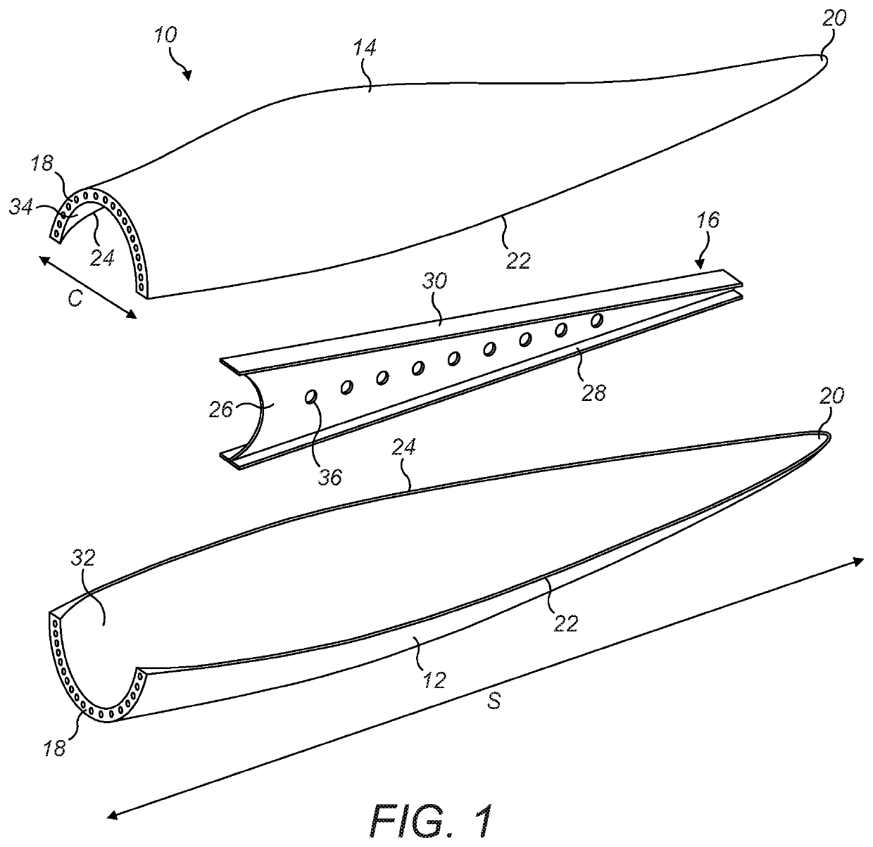
[0057]FIG. 1 is an exploded view of a wind turbine blade 10. The blade 10 comprises an outer shell formed of first and second half shells 12, 14, e.g. a windward half shell and a leeward half shell, and a single shear web 16. The half shells 12, 14 each extend longitudinally from a root end 18 to a tip end 20 in a spanwise direction, S, and extend between a leading edge 22 and a trailing edge 24 in a chordwise direction, C.

[0058]The shear web 16 is a longitudinally-extending structure, which in the illustrated example comprises a web panel 26 disposed between first and second mounting flanges 28, 30. In the orientation of the shear web 16 shown in the figures, the first mounting flange 28 is a ‘lower’ mounting flange, and the second mounting flange 30 is an ‘upper’ mounting flange. The mounting flanges 28, 30 are arranged transversely to the web-panel 26. When the blade is assembled (as will be discussed in further detail later), the mounting flanges 28, 30 are adhesively bonded to ...


PUM


Abstract

A method of making a wind turbine blade is described. The blade comprises first (12) and second (14) half shells bonded together and a shear web (16) bonded inside the shells. Prior to joining the shells together, the shear web is positioned in one of the shells. A plurality of bars (70) are attached to the shear web and engaged with a plurality of mounts (80) in order to support and stabilise the shear web relative to that shell. The shells are then arranged one above the other whilst the bars remain attached to the shear web. The bars continue to support the shear web whilst the shear web is aligned with the other shell. The bars are then detached from the shear web and the shells are brought together to bond the shells to each other and to bond the shear web between the shells.

Description

TECHNICAL FIELD[0001]The present invention relates generally to wind turbine blades, and more specifically to methods of making wind turbine blades and apparatus for use in such methods.BACKGROUND[0002]Modern wind turbine blades typically comprise a hollow shell made up of two half-shells bonded together along leading and trailing edges of the shells. One or more longitudinally-extending shear webs are provided within the internal cavity of the blade. A shear web comprises a web panel disposed between first and second mounting flanges. The mounting flanges are bonded respectively to opposed inner surfaces of the two half-shells.[0003]The method of making the blade typically involves forming the two half shells separately from composite materials in respective half-moulds of a blade mould assembly. A two-stage join up process may be used to connect the half shells together:[0004]In the first stage of the join-up, the shear web(s) are bonded to the inner surface of the first half shel...

Claims


Application Information

Patent Timeline
IPC IPC(8): B29D99/00F01D5/14F03D1/06B29C31/00
CPCF03D1/0675F01D5/141B29D99/0028F01D5/147B29C31/008B29C65/48B29L2031/085B29C65/7841B29C66/1122B29C66/1142B29C66/54B29C66/543B29C66/61B29C66/721B29C66/7212B29C66/8322B29C65/7805B29C66/636B29C65/7838B29K2309/08B29K2307/04
Inventor THOMSEN, PETER FRANS
Owner VESTAS WIND SYST AS
Why Eureka
Try Eureka