Control system for hybrid vehicle

a control system and hybrid technology, applied in the direction of automatic control of ignition, exhaust treatment, gearing, etc., can solve the problems of reduced purification performance of catalysts and insufficient warmed catalysts, and achieve the effect of efficient warmed catalysts

Active Publication Date: 2020-05-14
TOYOTA JIDOSHA KK
View PDF0 Cites 3 Cited by
  • Summary
  • Abstract
  • Description
  • Claims
  • Application Information

AI Technical Summary

Benefits of technology

[0006]Aspects of embodiments of the present disclosure have been conceived noting the foregoing technical problems, and it is therefore an object of the present disclosure to provide a control system for a hybrid vehicle that prevents a reduction in the purifying performance of the catalyst in a predetermined operating mode.
[0009]In a non-limiting embodiment, the controller may be further configured to raise the temperature of the purifying device by retarding an ignition timing of the engine.
[0015]Thus, according to the embodiment of the present disclosure, the shifting operation between the first hybrid vehicle mode and the second hybrid vehicle mode via the fixed mode is restricted if the purifying device is being warmed or the purifying device has to be warmed. According to the embodiment of the present disclosure, therefore, an operating point of the engine will not be shifted from the point at which the catalyst can be warmed up efficiently due to establishment of the fixed mode in which a speed ratio between the input element and the output element is fixed. For this reason, the catalyst can be warmed up promptly to purify exhaust gas.
[0017]As described, the operating point of the engine may be deviated from the point at which the catalyst can be warmed efficiently if the operating mode is shifted to the fixed mode. In order to prevent such disadvantage, the shifting operation between the first hybrid and the second hybrid mode via the fixed mode is restricted during the warm-up of the catalyst. However, the shifting operation between the first hybrid and the second hybrid mode via the fixed mode is allowed if the speed of the engine falls within the predetermined range suitable to warm the catalyst. In this case, the operating point of the engine will not be deviated significantly from the point at which the catalyst can be warmed efficiently even if the operating mode is shifted between the first hybrid and the second hybrid mode via the fixed mode. For this reason, the catalyst may be warmed efficiently even if the fixed mode is established temporarily.

Problems solved by technology

In this case, therefore, the catalyst may not be warmed up sufficiently and purifying performance of the catalyst may be reduced.

Method used


Image

  • Control system for hybrid vehicle
  • Control system for hybrid vehicle
  • Control system for hybrid vehicle

Examples


Embodiment Construction

)

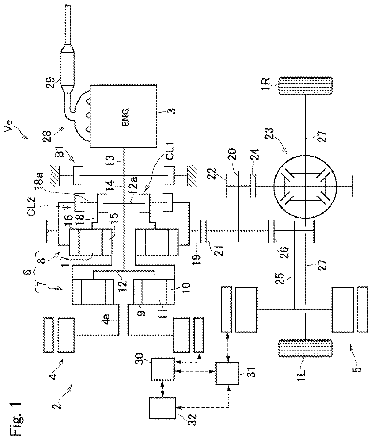
[0034]Preferred embodiments of the present application will now be explained with reference to the accompanying drawings. Referring now to FIG. 1, there is shown one example of a structure of a hybrid vehicle (as will be simply called the “vehicle” hereinafter) Ve to which the control system according to the embodiment is applied. Specifically, FIG. 1 shows a drive unit 2 of the vehicle Ve that drives a pair of front wheels 1R and 1L, and the drive unit 2 comprises an engine (referred to as “ENG” in the drawings) 3, a first motor (referred to as “MG1” in the drawings) 4, and a second motor (referred to as “MG2” in the drawings) 5. According to the exemplary embodiment, a motor-generator having a generating function is adopted as the first motor 4. In the vehicle Ve, a speed of the engine 3 is controlled by the first motor 4, and the second motor 5 is driven by electric power generated by the first motor 4 to generate a drive force for propelling the vehicle Ve. Optionally, the moto...


PUM


Abstract

A control system for a hybrid vehicle configured to prevent a reduction in the purifying performance of the catalyst in a predetermined operating mode. An operating mode of the hybrid vehicle can be selected from a first hybrid vehicle mode, a second hybrid vehicle mode, and a fixed mode. A controller that is configured to restrict a shifting operation between the first hybrid vehicle mode and the second hybrid vehicle mode via the fixed mode, when the purifying device is being warmed or the purifying device has to be warmed.

Description

CROSS-REFERENCE TO RELATED APPLICATIONS[0001]The present disclosure claims the benefit of Japanese Patent Application No. 2018-211753 filed on Nov. 9, 2018 with the Japanese Patent Office, the disclosures of which are incorporated herein by reference in its entirety.BACKGROUNDField of the Disclosure[0002]Embodiments of the present disclosure relate to the art of a control system for a hybrid vehicle in which a prime mover includes an engine and a motor.Discussion of the Related Art[0003]JP-A-2017-007437 describes a drive unit for a hybrid vehicle in which an output torque of an engine is distributed to a first motor and to an output side through a power split mechanism, and in which an output torque of a second motor driven by electricity supplied from the first motor is synthesized with the engine torque. In the hybrid vehicle taught by JP-A-2017-007437, an operating mode may be shifted by manipulating a first clutch and a second clutch of the drive unit. For example, in the hybrid...

Claims


Application Information

Patent Timeline
Patent Type & Authority Applications(United States)
IPC IPC(8): B60W20/20B60W20/10B60W10/06B60W10/08B60W10/115B60K6/365B60K6/442F01N13/00F16H48/06F16H37/08
CPCB60W2710/06F16H48/06F16H2200/20B60Y2300/18008F01N13/00B60W2710/10F16H2702/02B60W2510/06F01N2900/0602B60W20/20B60W10/115B60Y2200/92B60W2710/08B60K6/442B60W10/06F16H2200/0052F16H37/0806B60W20/10B60K6/365B60W10/08B60W20/16F02P5/15F02D41/024F02D29/02F01N2430/06F01N2430/00B60K6/445B60K6/387B60K2006/381B60K6/547B60W20/30B60W2510/0638B60W2540/10B60W2710/1005F01N3/2006F01N9/00F01N2590/11F01N2900/08F01N2900/10F01N2900/1404F01N2900/1602F01N2430/08Y02T10/12Y02T10/40
Inventor IMAMURA, TATSUYAAOKI, KAZUMAOSHIUMI, YASUHIROOKAMURA, YUKARI
Owner TOYOTA JIDOSHA KK
Why Eureka
Try Eureka