Vane rotary compressor

a compressor and rotary technology, applied in the field of compressors, can solve the problems of increasing mechanical efficiency, reducing mechanical efficiency, unstable rotation shaft, etc., and achieve the effects of enhancing the mechanical efficiency of the compressor, enhancing the reliability of the compressor, and enhancing the bearing

Active Publication Date: 2020-05-14
LG ELECTRONICS INC
View PDF0 Cites 1 Cited by
  • Summary
  • Abstract
  • Description
  • Claims
  • Application Information

AI Technical Summary

Benefits of technology

[0033]In a vane rotary compressor according to the present disclosure, as a bearing protrusion portion is formed on an inner circumferential side of a back pressure pocket facing a rotation shaft, a bearing surface of a shaft receiving portion that radially supports the rotation shaft can form a continuous surface. Further, an elastic bearing effect can be enhanced as the bearing protrusion portion forms a continuous surface. Accordingly, behavior of the rotation shaft can become stable so that mechanical efficiency of the compressor can be increased and abrasion on an inner circumferential surface of the bearing can be suppressed. This may result in enhancing reliability of the compressor.
[0034]In addition, since a communication flow path is formed in the bearing protrusion portion, oil of discharge pressure or pressure almost equal to discharge pressure, can be quickly and smoothly supplied to a high-pressure side back pressure pocket and pressure pulsation in the back pressure pocket can also be reduced. Accordingly, it is possible to provide stable back pressure to a relevant vane by supplying the high-pressure oil to a back pressure chamber connected to the high-pressure side back pressure pocket. This can prevent a vane related to a discharge stroke from being separated from the cylinder, thereby preventing leakage between compression chambers. In addition, behavior of the vane can be stabilized, thereby reducing noise from the compressor caused by vane vibration.
[0035]Also, abrasion on a bearing or the rotation shaft can be suppressed as the bearing protrusion portion prevents foreign materials from entering a bearing surface even during long-time operation, thereby enhancing reliability of the compressor.
[0036]In a vane rotary compressor according to the present disclosure, when a high-pressure refrigerant such as R32, R410a, and CO2 is used, radial support to the rotation shaft can be enhanced although surface pressure against a bearing is higher than that when a medium to low pressure refrigerant such as R134a is used. This may result in preventing leakage between compression chambers and stabilizing behavior of the vane, thereby enhancing reliability of the vane rotary compressor using the high-pressure refrigerant.
[0037]In addition, in a vane rotary compressor according to the present disclosure, radial supporting force to a rotation shaft can be enhanced even under a low-temperature heating condition, a high pressure ratio condition, and a high-speed operation condition.

Problems solved by technology

As a result, behavior of the rotation shaft becomes unstable and abrasion or frictional loss between the rotation shaft and the bearing is increased, thereby decreasing mechanical efficiency.
Further, pressure of the first pocket, opened between the bearing and the rotation shaft, is not constant, which leads to increased fluctuations in back pressure for supporting the vane.
Accordingly, behavior of the vane becomes unstable, and collision noise between the vane and the cylinder or leakage between compression chambers is increased.
Furthermore, there is a possibility of abrasion on the bearing surface caused by foreign materials accumulated in the first pocket opened between the bearing and the rotation shaft during long-time operation.
This may be particularly problematic for the related art vane rotary compressor when a high-pressure refrigerant such as R32, R410a, and CO2 is used.
As a result, a bearing surface on the rotation shaft is reduced, which makes behavior of the rotation shaft more unstable, leading to a further increase in mechanical friction loss.

Method used


Image

  • Vane rotary compressor
  • Vane rotary compressor
  • Vane rotary compressor

Examples


Embodiment Construction

[0051]Description will now be given in detail of a vane rotary compressor according to exemplary embodiments disclosed herein, with reference to the accompanying drawings.

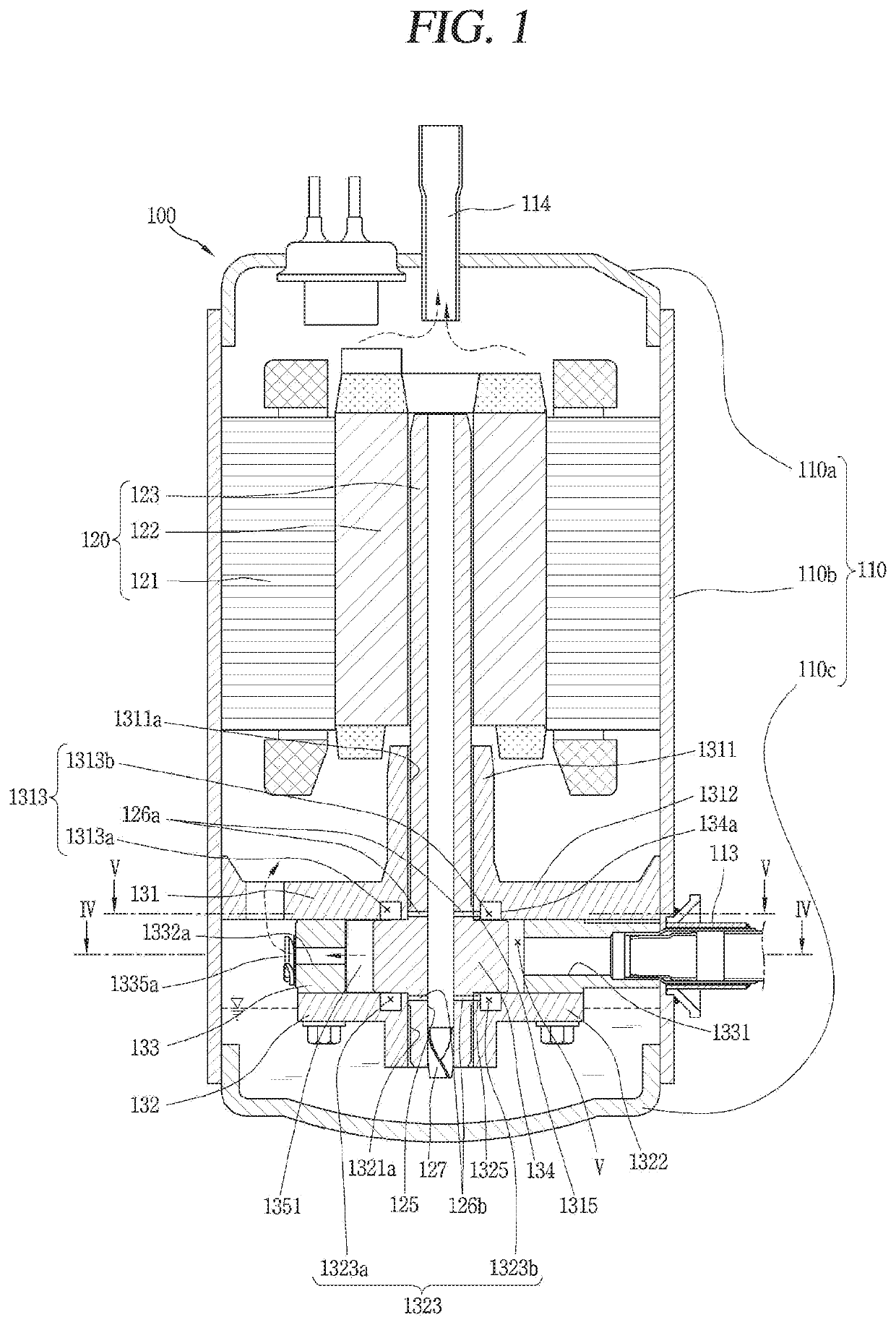
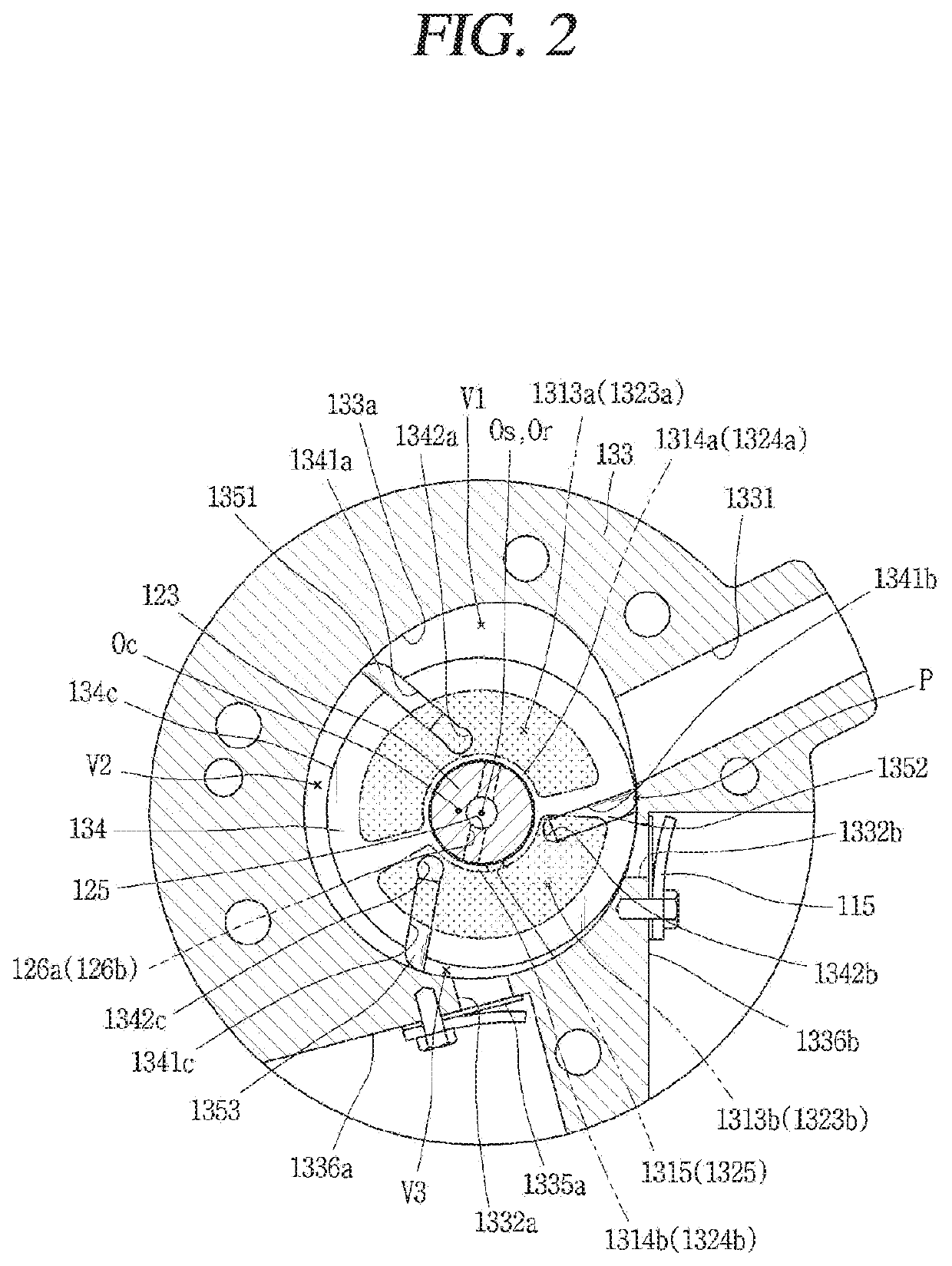
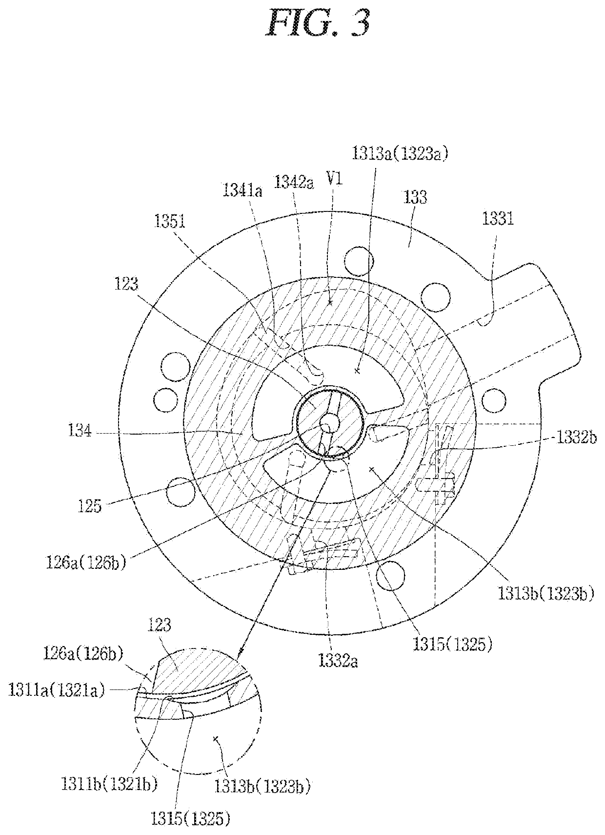
[0052]FIG. 1 is a longitudinal sectional view of an exemplary vane rotary compressor according to the present disclosure, and FIGS. 2 and 3 are horizontal sectional views of a compression unit of FIG. 1. FIG. 2 is a sectional view taken along line “IV-IV” of FIG. 1, and FIG. 3 is a sectional view taken along line “V-V” of FIG. 2.

[0053]Referring to FIG. 1, a vane rotary compressor according to the present disclosure includes a driving motor 120 installed in a casing 110 and a compression unit 130 provided at one side of the driving motor 120 and mechanically connected to each other by a rotation shaft 123.

[0054]The casing 110 may be classified as a vertical type or a horizontal type according to a compressor installation method. As for the vertical-type casing, the driving motor and the compression unit are disposed...


PUM


Abstract

A vane rotary compressor has a cylinder. A main bearing and a sub bearing are coupled to the cylinder forming a compression space. The main and sub bearing each have a back pressure pocket on a surface facing the cylinder. The main bearing and the sub bearing radially support a rotation shaft. A roller coupled to the shaft is disposed within the compression space. The roller has circumferentially spaced vane slots, each vane slot extending from an open end on an outer circumferential surface of the roller to a back pressure chamber disposed within the roller at an opposite end of each vane slot. A plurality of vanes slide within the vane slots and divide the compression space into compression chambers. At least one of the back pressure chambers in the vane slots fluidly communicates with at least one of the back pressure pockets in the main and sub bearings.

Description

CROSS-REFERENCE TO RELATED APPLICATION[0001]Pursuant to 35 U.S.C. § 119(a), this application claims the benefit of earlier filing date and right of priority to Korean Application No. 10-2018-0137651, filed on Nov. 9, 2018, the contents of which are incorporated by reference herein in their entirety.BACKGROUND OF THE DISCLOSURE1. Field of the Disclosure[0002]The present disclosure relates to a compressor, more particularly, a vane rotary compressor in which a vane protruding from a rotating roller comes in contact with an inner circumferential surface of a cylinder to form a compression chamber.2. Background Art[0003]A rotary compressor can be divided into two types, namely, a type in which a vane is slidably inserted into a cylinder to come in contact with a roller, and another type in which a vane is slidably inserted into a roller to come in contact with a cylinder. Normally, the former is referred to as a ‘rotary compressor’ and the latter is referred to as a ‘vane rotary compres...

Claims


Application Information

Patent Timeline
Patent Type & Authority Applications(United States)
IPC IPC(8): F04C18/344
CPCF04C2210/26F04C18/3445F04C29/025F04C18/3442F01C21/0872F04C2210/261F04C2210/268F04C2240/56F04C18/344F04C29/028F04C29/023F04C29/06F04C2240/50F04C2240/603
Inventor PARK, JOONHONGKANG, SEOUNGMINCHOI, SEHEON
Owner LG ELECTRONICS INC
Why Eureka
Try Eureka