

Multi-depth exit pupil expander
- Summary
- Abstract
- Description
- Claims
- Application Information
AI Technical Summary
Benefits of technology
Problems solved by technology
Method used
Image

Examples
Embodiment Construction
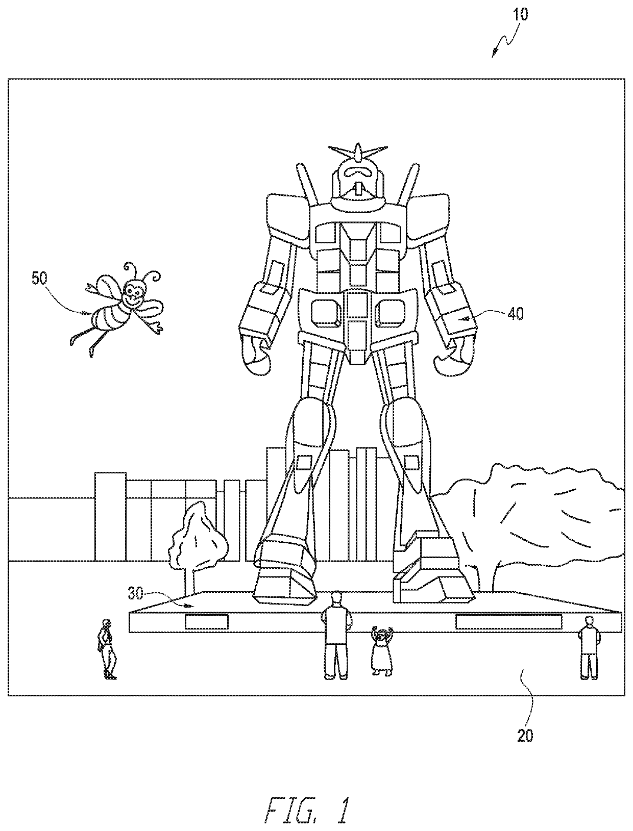
[0150]Reference will now be made to the figures, in which like reference numerals refer to like parts throughout. It will be appreciated that embodiments disclosed herein include optical systems, including display systems, generally. In some embodiments, the display systems are wearable, which may advantageously provide a more immersive VR or AR experience. For example, displays containing one or more waveguides (e.g., a stack of waveguides) may be configured to be worn positioned in front of the eyes of a user, or viewer. In some embodiments, two stacks of waveguides, one for each eye of a viewer, may be utilized to provide different images to each eye.
Example Display Systems
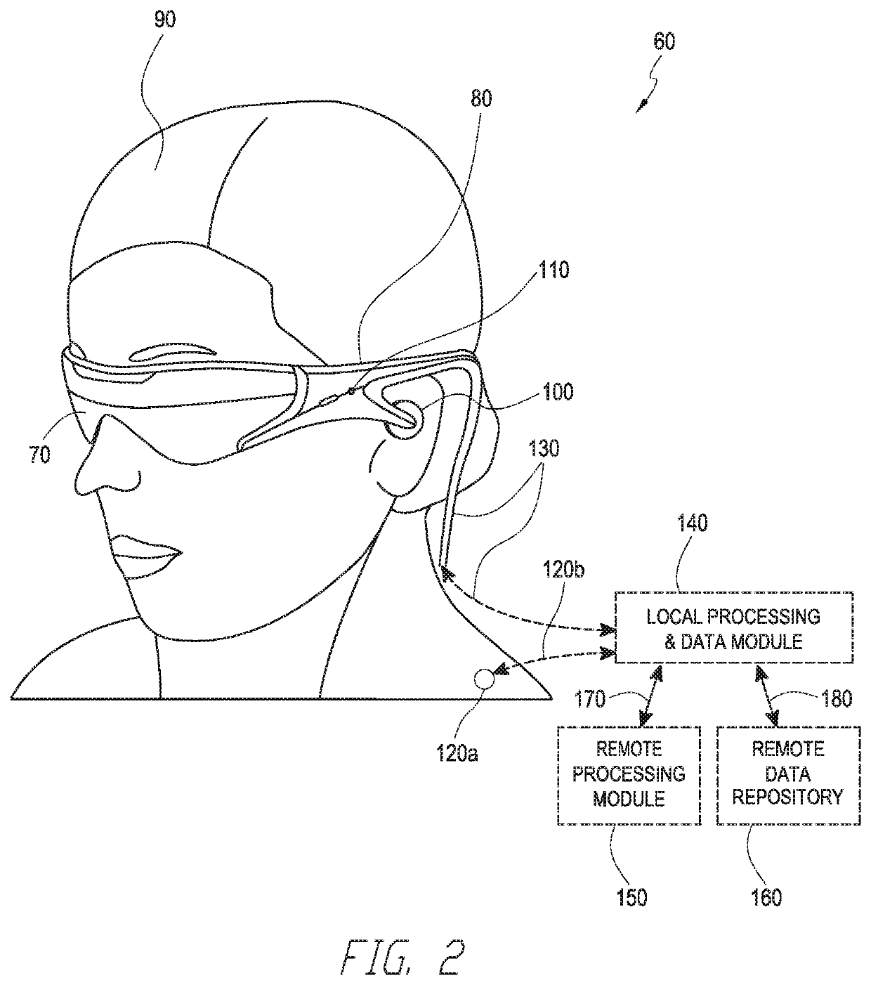
[0151]FIG. 2 illustrates an example of wearable display system 60. The display system 60 includes a display 70, and various mechanical and electronic modules and systems to support the functioning of that display 70. The display 70 may be coupled to a frame 80, which is wearable by a display system user or view...
PUM
 Abstract
Description
Claims
Application Information