
Milling system and method under different lubrication conditions

Active Publication Date: 2020-05-28
QINGDAO TECHNOLOGICAL UNIVERSITY +2
View PDF0 Cites 3 Cited by
  • Summary
  • Abstract
  • Description
  • Claims
  • Application Information

AI Technical Summary

Benefits of technology

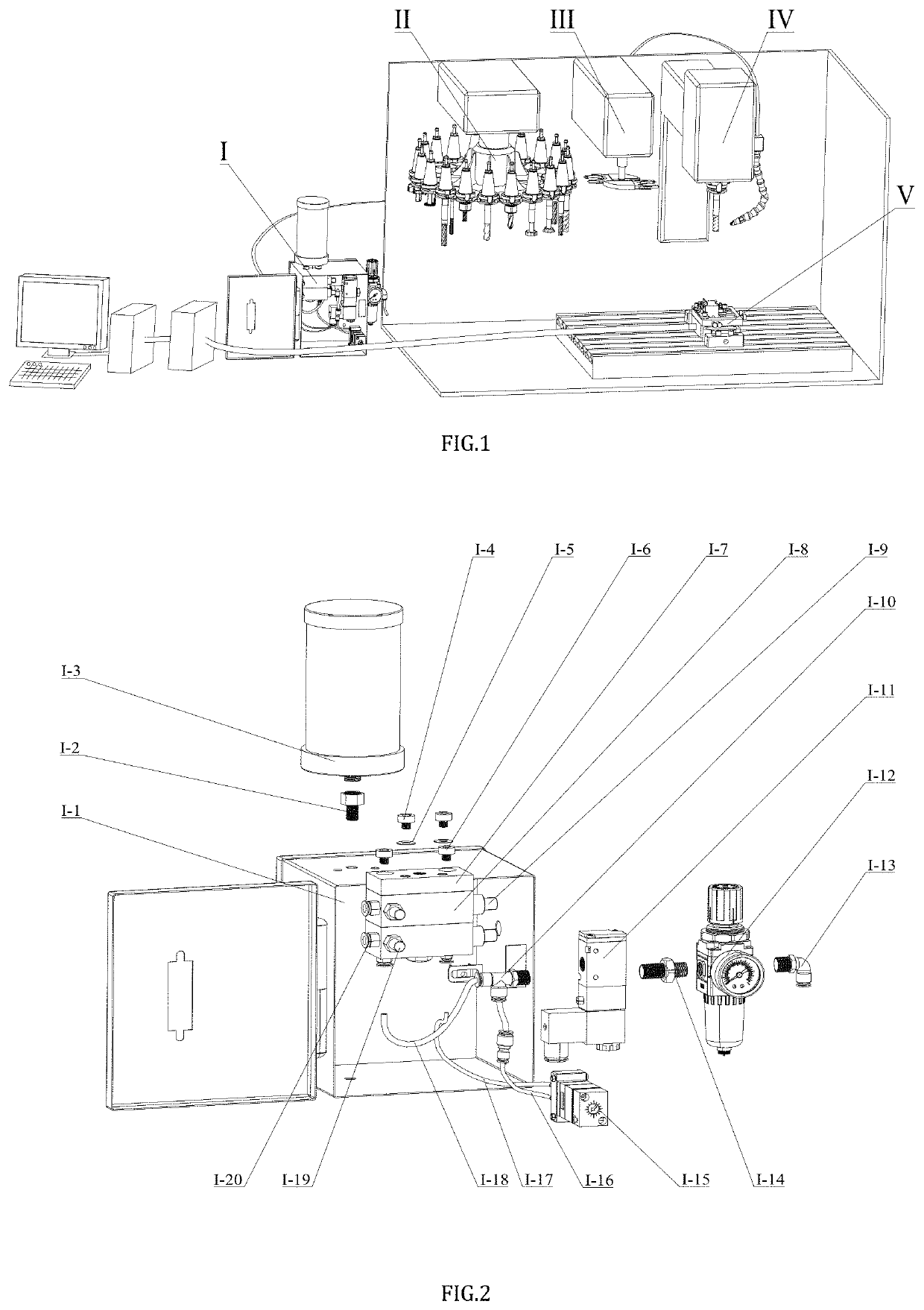
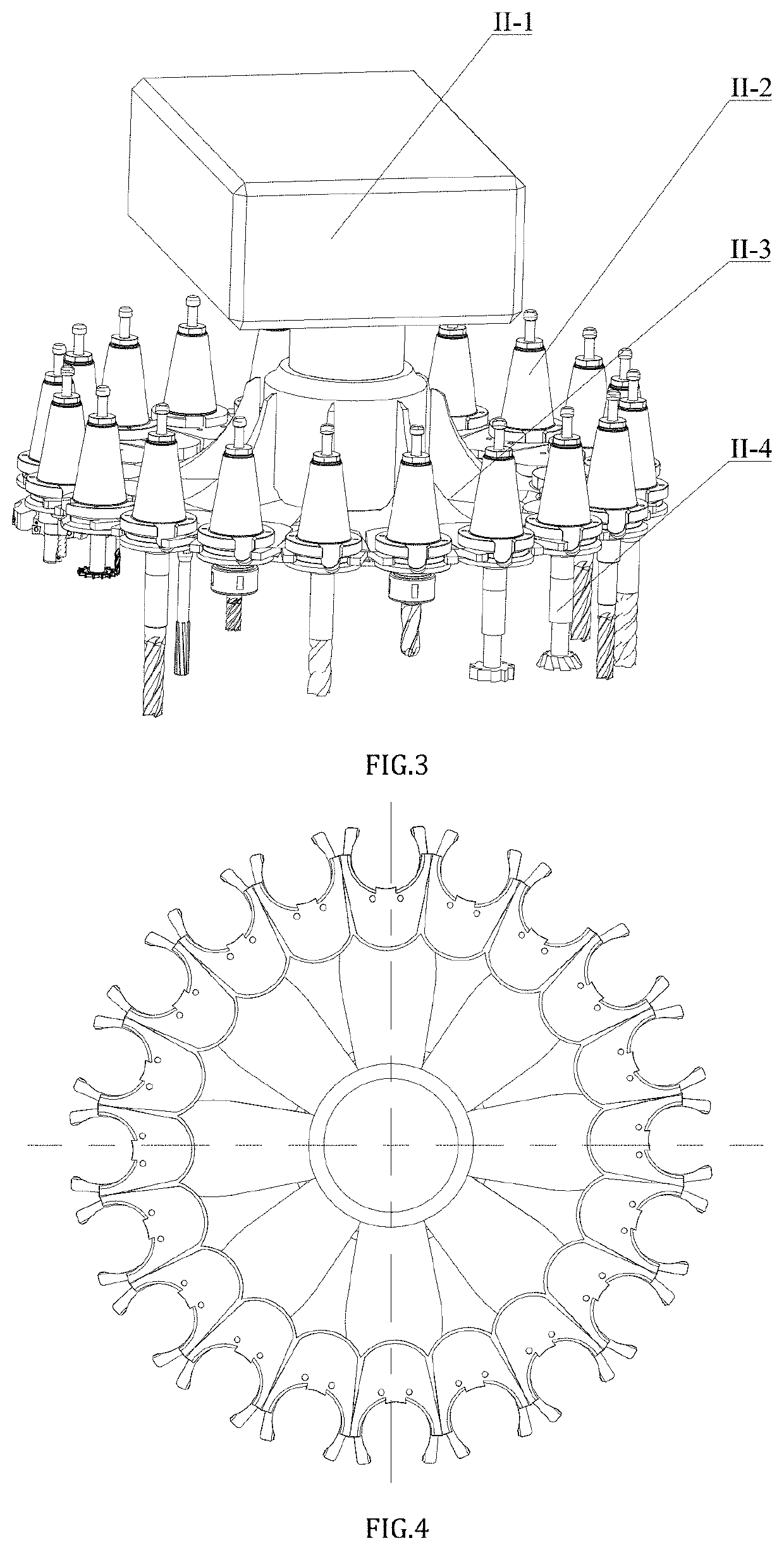
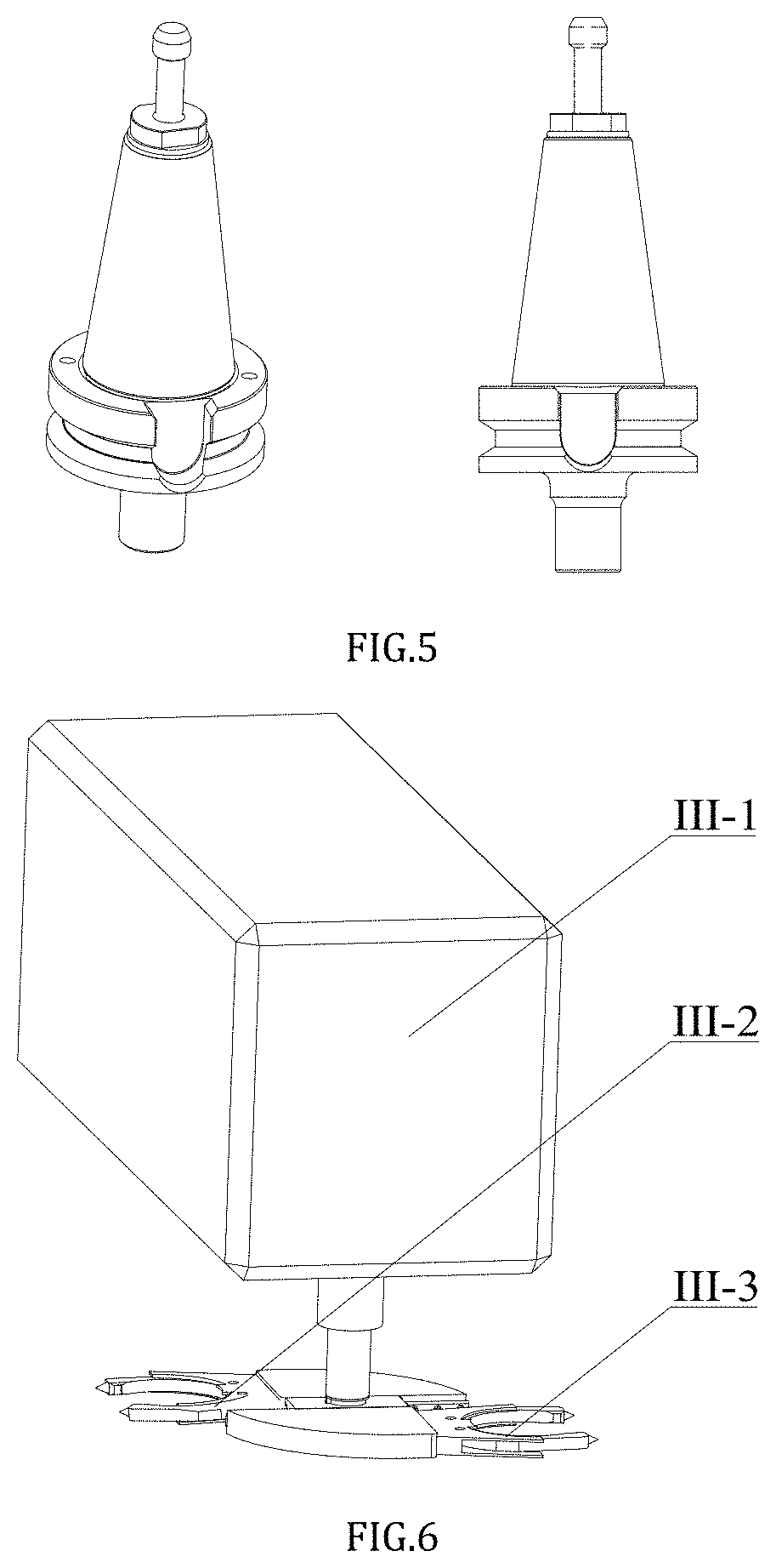
The patent describes a method and system for milling injected cutting fluid under different working conditions. This system includes a milling cutter, a force measurement instrument, a cutter change system, a magazine system, and a lubricating system. The position of a nozzle is selected based on airflow fields under different working conditions to improve the efficiency of the cutting fluid. The nozzle is located in the incoming flow and is not affected by breaking through the air barrier, thereby saving energy. The position of the nozzle can be adjusted to improve the transportation effect of the airflow field on the cutting fluid and increase the efficiency of the cutting fluid. The cutting system includes a mandrel and a workpiece holder with clamping elements in three directions to meet the requirement on change in the size of the workpiece. The method and system provide a way to save energy and improve the efficiency of the cutting fluid.

Problems solved by technology

However, when in milling, the contact time between a cutter and a workpiece is extremely short, the sharp friction occurs between the rake face of the cutter and the chips and between the flank face of the cutter and the workpiece so that a large number of cutting heat is generated, the cutter is sharply abraded, cutter failure is too fast, and the improvement of the processing efficiency is seriously restricted.
The conventional milling causes huge damage on environment and workers due to use of a large amount of cutting fluid.
However, this fluid supply method has certain disadvantages that the air has viscidity, the milling cutter rotating at high speed can affect the hydrodynamic characteristics of an air flow field close to the milling cutter, the air around the milling cutter is originally static, but the milling cutter rotating at high speed can cause air to flow, and the closer the air is to the cutting edge, the higher the flow speed of air is, thus forming a closed “ring-shaped” area around the milling cutter, which hinders the incoming of the cutting fluid so that the cutting fluid cannot enter the milling cutter / workpiece interface to cause machining burns.
However, at present, there are no good research achievements in the aspect of cutting fluid injection during milling.

Method used


Image

  • Milling system and method under different lubrication conditions
  • Milling system and method under different lubrication conditions
  • Milling system and method under different lubrication conditions

Examples


Embodiment Construction

[0065]The disclosure will be further described in combination with drawings and embodiments.

[0066]It should be noted that the following descriptions are all illustrative, and intended to provide further description for this application. Unless indicated otherwise, all the technical terms and scientific terms used in this text have the same meaning as that understood by those of ordinary skill in the art.

[0067]It is noted that the terms used herein are only for describing specific embodiments and are not intended to limit exemplary embodiments according to this application. As used herein, the singular is intended to include the plural, unless the context otherwise expressly indicates. In addition, it is also understood that when the terms “include” and / or “comprise” are used in this description, they indicate that there are features, steps, operations, devices, components and / or their combinations.

[0068]In the disclosure, the orientation or position relationship indicated by terms s...


PUM


Abstract

The disclosure provides a method and system for milling injected cutting fluid under different working conditions. By analyzing influence of airflow fields in a milling area under different working conditions on injection of cutting fluid, an influence rule of a helical angle and a rotation speed of a cutter on the flow field is quantitatively analyzed, an optimal target distance of a nozzle, an angle between the nozzle and a milling cutter feeding direction and an angle between the nozzle and the surface of a workpiece are comprehensively determined, the nozzle is set according to a determined setting manner, and lubricating oil is sprayed to the milling area by utilizing the nozzle.

Description

CROSS-REFERENCE TO RELATED APPLICATIONS[0001]This application claims priority to Chinese Patent Application No. 201811401223.3 with a filing date of Nov. 22, 2018. The content of the aforementioned applications, including any intervening amendments thereto, are incorporated herein by reference.TECHNICAL FIELD[0002]The disclosure relates to a method and system for milling injected cutting fluid under different working conditions.BACKGROUND OF THE PRESENT INVENTION[0003]The statement of this part only provides background technical information related to the present disclosure, and does not necessarily constitute the existing technology.[0004]At present, milling is the most commonly used cutting in mechanical manufacturing industry, which is high in processing and production efficiency, wide in processing target distance and high in processing precision. However, when in milling, the contact time between a cutter and a workpiece is extremely short, the sharp friction occurs between the...

Claims


Application Information

Patent Timeline
IPC IPC(8): B23Q11/10B23C1/06B23Q3/157B23Q3/155
CPCB23Q2003/155418B23Q11/10B23C1/06B23Q3/1554B23Q2003/155428B23C2250/12B23Q3/15722B23Q3/06B23Q11/1038B23Q17/005B23Q11/1076B23Q17/0966B23Q3/15713B23Q11/1046G05B19/042G05B2219/37355Y02P70/10G05B2219/35181G05B2219/50248
Inventor LI, CHANGHEYIN, QINGANCAO, HUAJUNLIU, YONGHONGDING, WENFENGZHANG, NAIQINGDONG, LANDUAN, ZHENJINGZHANG, YANBINBAI, XIUFANGSUI, MENGHUAWU, WENTAOTENG, GAOYANG, MINJIA, DONGZHOULI, RUNZEHOU, YALI
Owner QINGDAO TECHNOLOGICAL UNIVERSITY
Learn More