Printing press

a printing press and press body technology, applied in printing, power drive mechanisms, other printing apparatuses, etc., can solve the problem that conventional transport systems cannot always be used with particularly thick sheets

Active Publication Date: 2020-05-28
KOENIG & BAUER AG
View PDF0 Cites 1 Cited by
  • Summary
  • Abstract
  • Description
  • Claims
  • Application Information

AI Technical Summary

Benefits of technology

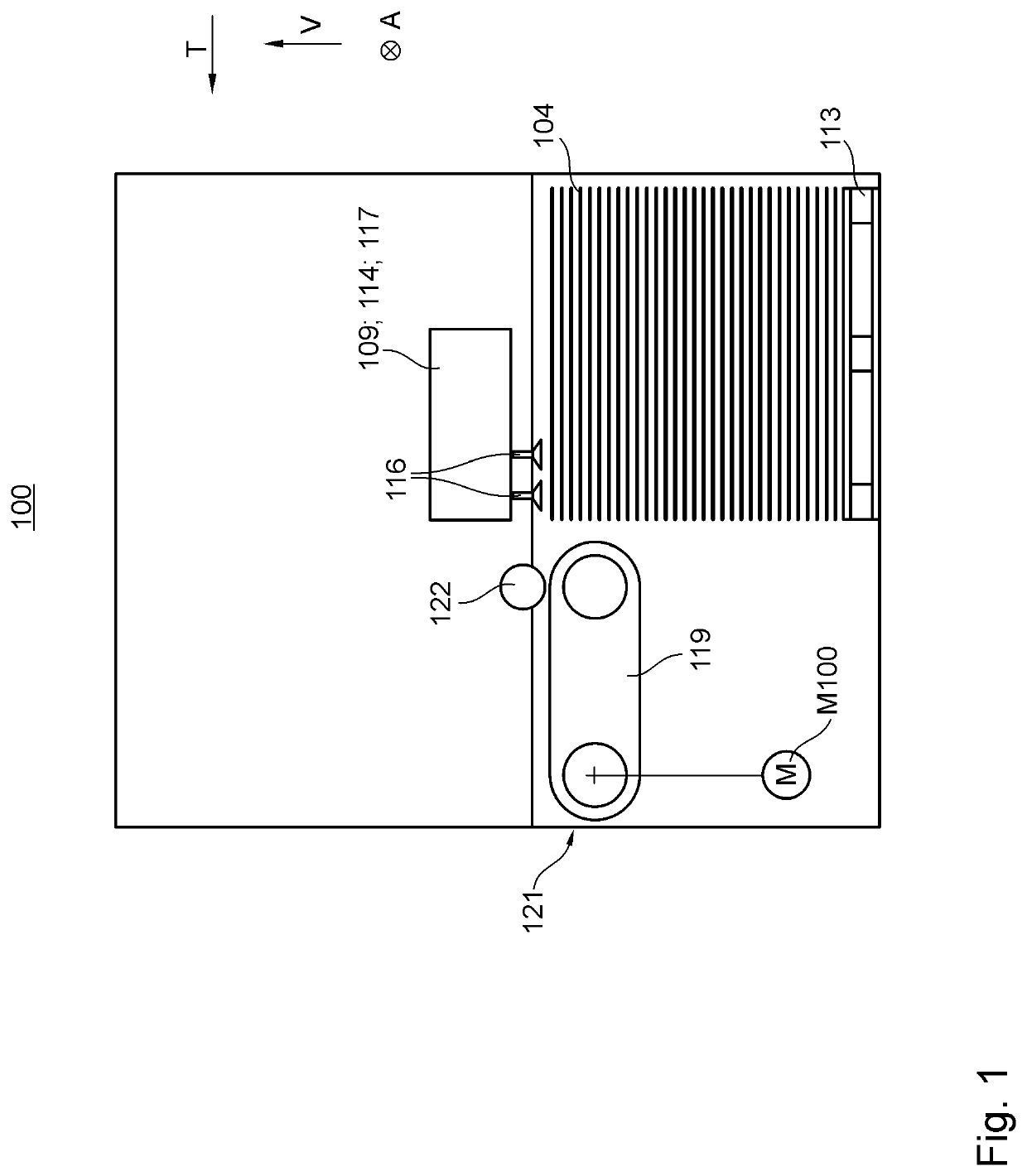
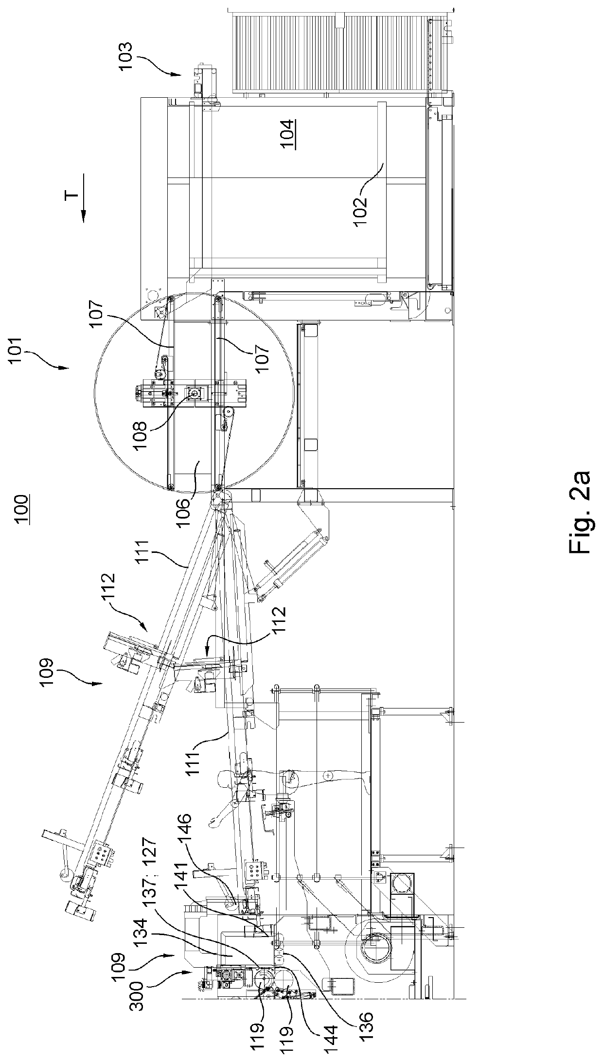
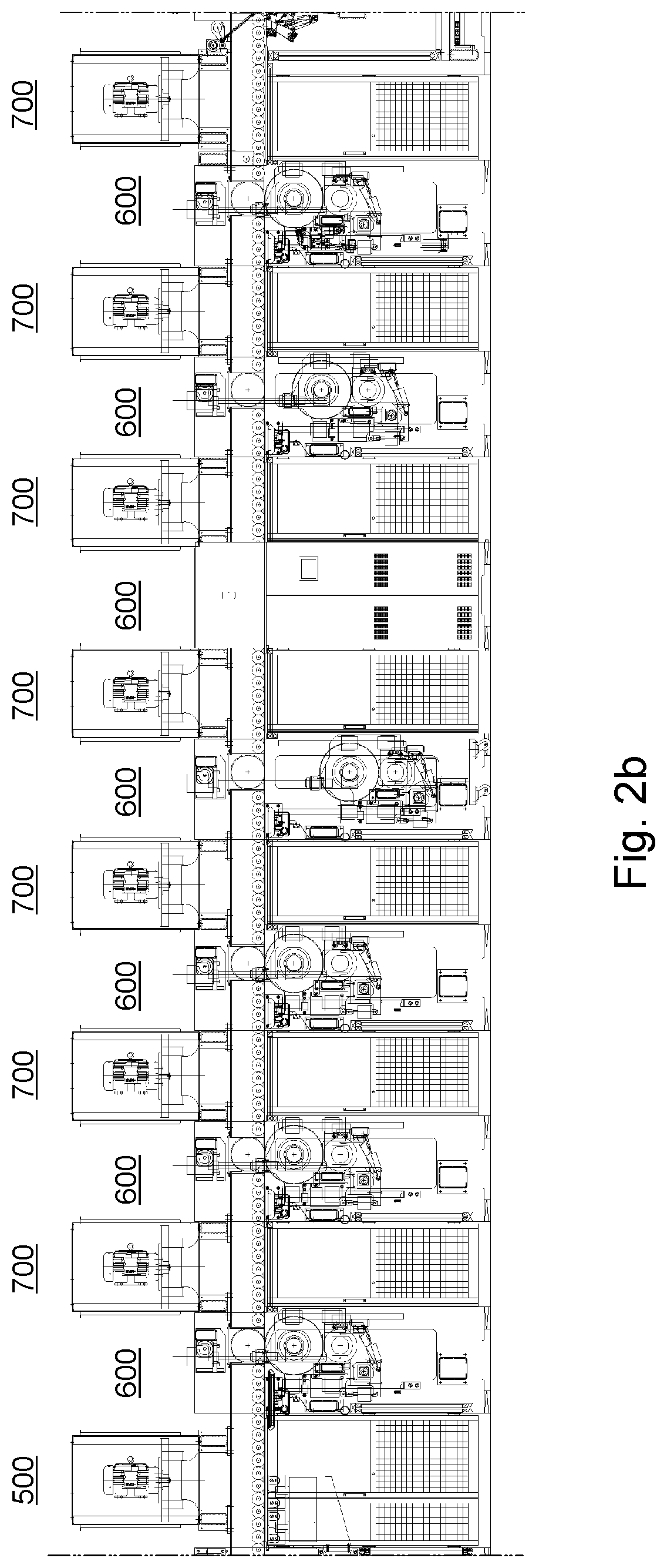
[0017]The object of the present invention is to devise a printing press. The object is attained according to the invention by the provision of a printing press, which comprises at least two units configured as modules. At least one of the at least two modules is configured as a non-impact coating module. The at least one non-impact coating module has at least one print head. Each of the at least two modules has at least one drive dedicated uniquely to it, each drive serving to effect a transport of substrate through the respective module or through at least one zone of action of the respective module. Along a transport path provided for a transport of substrate, at least one first application point of at least one non-impact coating module, which is intended for colored coating medium, is located, followed downstream by an exposure zone of at least one drying device, which is assigned to the fir

Problems solved by technology

However, conventional transport systems cannot

Method used


Image

  • Printing press
  • Printing press
  • Printing press

Examples


first embodiment

[0158]a suction transport means 111; 117; 119; 136; 211; 311; 411; 417; 511; 561; 611; 617; 711; 811; 817; 911; 1011 is a suction belt 111; 117; 119; 136; 211; 311; 411; 417; 511; 561; 611; 617; 711; 811; 817; 911; 1011. In this context, a suction belt 111; 117; 119; 136; 211; 311; 411; 417; 511; 561; 611; 617; 711; 811; 817; 911; 1011 is understood as a system having at least one flexible conveyor belt 718; 726, which serves as a transport surface 718. The at least one conveyor belt 718; 726 is preferably deflected by deflection means 724 configured as deflection rollers 724 and / or deflection cylinders 724 and / or is preferably closed, so that continuous circulation is possible. The at least one conveyor belt 718; 726 preferably has a multiplicity of suctioning openings 723. Over at least a portion of its circulation path, the at least one conveyor belt 718; 726 preferably covers the at least one suction opening 722 of the at least one vacuum chamber 719. In that case, vacuum chambe...

second embodiment

[0159]a suction transport means 111; 117; 119; 136; 211; 311; 411; 417; 511; 561; 611; 617; 711; 811; 817; 911; 1011 is a suction box belt 111; 117; 119; 136; 211; 311; 411; 417; 511; 561; 611; 617; 711; 811; 817; 911; 1011. A suction box belt 111; 117; 119; 136; 211; 311; 411; 417; 511; 561; 611; 617; 711; 811; 817; 911; 1011 is understood as a system that comprises a plurality of suction boxes 718; 727, each having an outer surface 718 that serves as a transport surface 718. Each of the suction boxes 718; 727 preferably has at least one suction chamber 728. The respective suction chamber 728 is preferably open outward in one direction through at least one flow opening 729. This at least one flow opening 729 preferably serves to conduct a negative pressure from the vacuum chamber 719 into the respective suction chamber 728. The at least one flow opening 729 is positioned laterally, for example, or is positioned such that it faces at least intermittently in or opposite a vertical di...

third embodiment

[0161]a suction transport means 111; 117; 119; 136; 211; 311; 411; 417; 511; 561; 611; 617; 711; 811; 817; 911; 1011 is a roller suction system 111; 117; 119; 136; 211; 311; 411; 417; 511; 561; 611; 617; 711; 811; 817; 911; 1011. A roller suction system 111; 117; 119; 136; 211; 311; 411; 417; 511; 561; 611; 617; 711; 811; 817; 911; 1011 is understood as a system in which the at least one transport surface 718 is composed of at least parts of lateral surfaces 718 of a multiplicity of transport rollers 724 and / or transport cylinders 724. The transport rollers 724 and / or transport cylinders 724 each form closed parts of the transport surface 718 that circulate by rotation. The roller suction system 111; 117; 119; 136; 211; 311; 411; 417; 511; 561; 611; 617; 711; 811; 817; 911; 1011 preferably has a multiplicity of suction openings 722. These suction openings 722 are preferably arranged at least between adjacent transport rollers 724 and / or transport cylinders 724.

[0162]At least one cov...


PUM


Abstract

A printing press has at least two units in the form of modules, at least one of which is in the form of a non-impact coating module and has at least one print head. The at least two modules each have at least one dedicated drive which is used to effect transport of a substrate through the module or through an effective region of the module. Along an intended transport path, there is at least one first application point, provided for the application of a color coating agent, an effective region of at least one drying device assigned to the first application point and at least one further application point provided for color coating agent application, and further oriented towards the same side, of at least one non-impact coating module, and an effective region of at least one further drying device assigned to the further application point. At least one print head is preferably one of connected and connectable to at least one positioning device. The at least one positioning device preferably has at least one positioning drive.

Description

CROSS REFERENCE TO RELATED APPLICATIONS[0001]This application is the U.S. National Phase, under 35 U.S.C. § 371, of PCT / EP2017 / 079636, filed Nov. 17, 2017; published as WO 2018 / 133976 A1 on Jul. 26, 2018, and claiming priority to DE 10 2017 201 012.6, filed Jan. 23, 2017; to DE 10 2017 208 738.2, filed May 23, 2017 and to DE 10 2017 212 981.6, filed Jul. 17, 2017, the disclosures of which are expressly incorporated herein in their entireties by reference.FIELD OF THE INVENTION[0002]The present invention relates to a printing press.BACKGROUND OF THE INVENTION[0003]A number of different printing methods are used in printing presses. Non-impact printing (NIP) methods are understood as printing methods that do not require a fixed, that is to say, a physically unalterable printing forme. Printing methods of this type are able to produce different printed images in each printing operation. Examples of non-impact printing methods include ionographic methods, magnetographic methods, thermog...

Claims


Application Information

Patent Timeline
IPC IPC(8): B41J11/00
CPCB41J11/0085B41J2/165B41J2/16585B41J11/002B41J11/0035B41J13/0027B41J25/304B41J25/308
Inventor BERNARD, ANDREASBREUNIG, HARTMUTHUPPMANN, FRANKMASUCH, BERND
Owner KOENIG & BAUER AG
Why Eureka
Try Eureka