
Aerofoil stagnation zone cooling

a technology of aerofoil and stagnation zone, which is applied in the manufacture of engines, mechanical equipment, machines/engines, etc., can solve the problems of edge cracking or holes in the aerofoil, damage to the aerofoil zone, and further damage to the aerofoil

Active Publication Date: 2020-05-28
ROLLS ROYCE PLC
View PDF0 Cites 6 Cited by
  • Summary
  • Abstract
  • Description
  • Claims
  • Application Information

AI Technical Summary

Benefits of technology

The present patent describes an aerofoil for a gas turbine engine that includes a pressure surface, a suction surface, a leading edge, a trailing edge, a stagnation zone located at the leading edge, and an elongate channel running along the leading edge. The elongate channel has a cross section that may vary along its length. The aerofoil may also have cooling holes directed to the elongate channel. The elongate channel may be designed to direct cooling air to the leading edge and stagnation zone. The aerofoil may be used in a gas turbine engine with a gearbox that drives the fan at a lower rotational speed than the core shaft. The engine may also have multiple stages in each compressor. The technical effects of the invention include improved cooling efficiency, reduced pressure drop, and improved performance and reliability of the gas turbine engine.

Problems solved by technology

However, because of the lack of film cooling at the stagnation zone, this zone of the aerofoil may be subject to being damaged by heat.
For example, for an aerofoil which is coated with a thermal barrier coating (TBC), this coating may be damaged in the stagnation zone, which can then lead to further damage of the aerofoil, such as spallation, followed by leading edge cracking or holes being formed in the aerofoil.

Method used


Image

  • Aerofoil stagnation zone cooling
  • Aerofoil stagnation zone cooling
  • Aerofoil stagnation zone cooling

Examples


Embodiment Construction

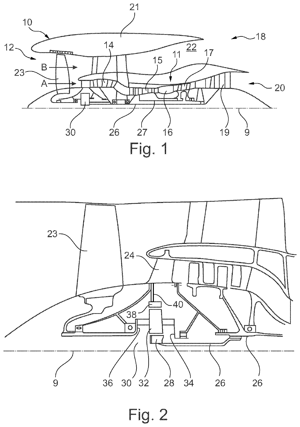
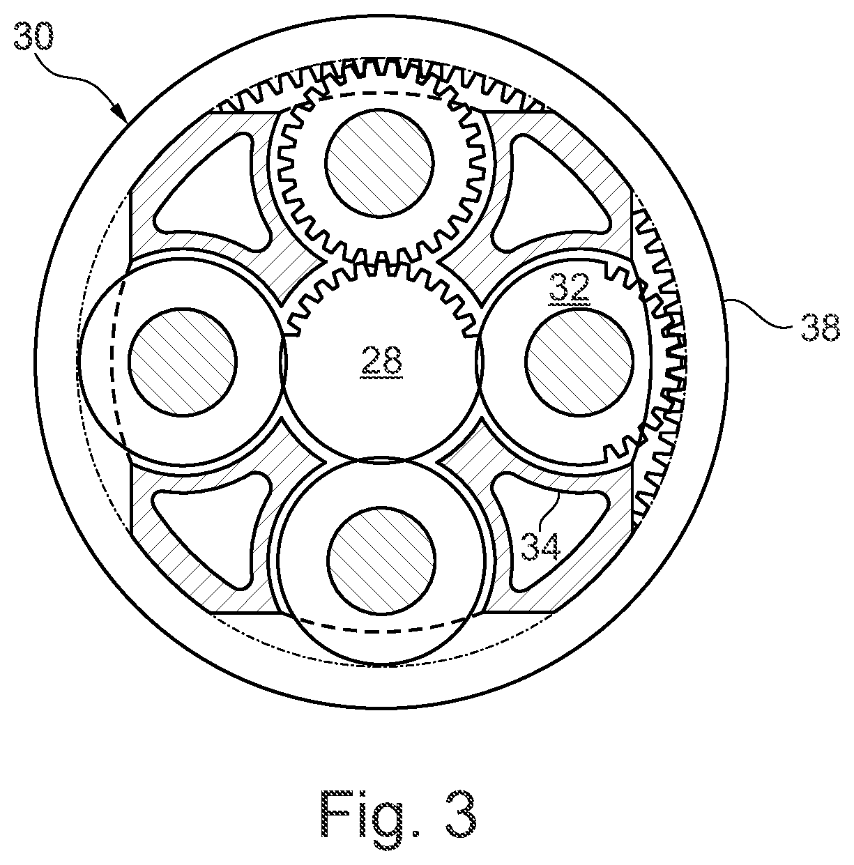
[0057]FIG. 1 illustrates a gas turbine engine 10 having a principal rotational axis 9. The engine 10 comprises an air intake 12 and a propulsive fan 23 that generates two airflows: a core airflow A and a bypass airflow B. The gas turbine engine 10 comprises a core 11 that receives the core airflow A. The engine core 11 comprises, in axial flow series, a low pressure compressor 14, a high-pressure compressor 15, combustion equipment 16, a high-pressure turbine 17, a low pressure turbine 19 and a core exhaust nozzle 20. A nacelle 21 surrounds the gas turbine engine 10 and defines a bypass duct 22 and a bypass exhaust nozzle 18. The bypass airflow B flows through the bypass duct 22. The fan 23 is attached to and driven by the low pressure turbine 19 via a shaft 26 and an epicyclic gearbox 30.

[0058]In use, the core airflow A is accelerated and compressed by the low pressure compressor 14 and directed into the high pressure compressor 15 where further compression takes place. The compres...


PUM


Abstract

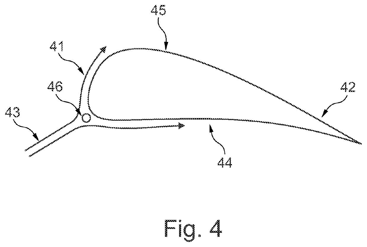
An aerofoil and an aerofoil assembly, in particular an aerofoil with improved stagnation zone cooling and an aerofoil assembly comprising such an aerofoil. The aerofoil is an aerofoil for a gas turbine engine comprising a pressure surface, a suction surface, a leading edge, a trailing edge, a stagnation zone located in the region of the leading edge, and an elongate channel running along the leading edge at the stagnation zone.

Description

CROSS-REFERENCE TO RELATED APPLICATIONS[0001]This application is based upon and claims the benefit of priority from British Patent Application No. GB 1819064.5, filed on 23 Nov. 2018, the entire contents of which are incorporated herein by reference.BACKGROUNDTechnical Field[0002]The present disclosure relates to an aerofoil and an aerofoil assembly, in particular an aerofoil with improved stagnation zone cooling and an aerofoil assembly comprising such an aerofoil.Description of the Related Art[0003]Gas turbine engines typically comprise a large number of aerofoils in both the compressor and turbine. Each of the compressor and turbine may include plural rows of stationary aerofoils (stators) and moving aerofoil blades (rotors). A typical aerofoil has a leading edge which is impinged by a gas flow, a trailing edge over which the flow exits, and a pressure surface and suction surface. When gas flows across the aerofoil, the gas pressure is higher on the pressure surface than on the s...

Claims


Application Information

Patent Timeline
Patent Type & Authority Applications(United States)
IPC IPC(8): F02C7/36F01D5/12
CPCF02C7/36F05D2240/60F01D5/12F05D2220/32F01D5/141F01D5/145F05D2240/121F05D2240/303F05D2240/81F05D2250/294Y02T50/60
Inventor SADDAWI, SALWAN D.
Owner ROLLS ROYCE PLC
Learn More