
Liquid crystal display panel and terminal device

a terminal device and liquid crystal technology, applied in the field of display technologies, to achieve the effect of improving the shooting performance of the camera and avoiding the effect of affecting the imaging of the camera

Active Publication Date: 2020-05-28
WUHAN CHINA STAR OPTOELECTRONICS TECH CO LTD
View PDF5 Cites 6 Cited by
  • Summary
  • Abstract
  • Description
  • Claims
  • Application Information

AI Technical Summary

Benefits of technology

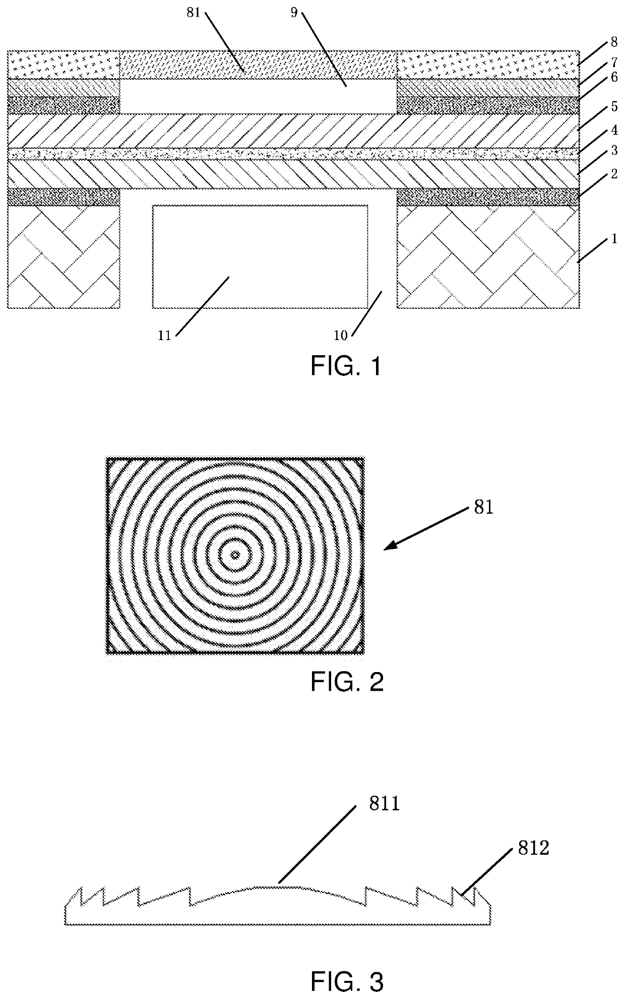
The present invention solves the problem of low light transparency in current blind hole designs by providing a liquid crystal display panel with a Fresnel lens. The Fresnel lens light into parallel or concentrating light that enters the camera through the first blind hole, a color filter, a liquid crystal layer, a TFT layer, and a second blind hole. As a result, the light transmissivity at the cover glass is increased, improving camera shooting performance without affecting the imaging of the camera.

Problems solved by technology

The through hole mainly requires special considerations such as process complexity, cost, and glass strength.

Method used


Image

  • Liquid crystal display panel and terminal device

Examples


Embodiment Construction

[0021]The preferred embodiments of the present disclosure are described in detail below with reference to the accompanying drawings, in which those skilled in the art will more readily understand how to implement the disclosure. The present disclosure, however, may be embodied in many different forms of embodiments, and the scope of the present disclosure is not limited to the embodiments described herein. The description of the embodiments below is not intended to limit the scope of the present disclosure.

[0022]Directional terms mentioned in the present disclosure, such as “top”, “bottom”, “front”, “rear”, “left”, “right”, “inside”, “outside”, “side”, etc., are only directional terms used in the drawings. The directional terms used herein are used to explain and explain the present disclosure and are not intended to limit the scope of the present disclosure.

[0023]In the drawings, structurally identical components are denoted by same reference numerals, and structural or functionall...


PUM

PropertyMeasurementUnit
radiusaaaaaaaaaa
radiusaaaaaaaaaa
electric fieldaaaaaaaaaa

Abstract

A liquid crystal display panel and a terminal device are provided. The liquid crystal display panel includes a backlight module, a lower polarizer, a thin film transistor (TFT) layer, a liquid crystal layer, a color filter, an upper polarizer, an optical adhesive, and a cover glass which are sequentially disposed. A Fresnel lens is disposed at a position corresponding to a first blind hole by one or more of a computerized numerical control (CNC) machining, a glass injection molding, and a casting. The liquid crystal display panel adjusts externally incoming light into parallel light or concentrating light by providing the Fresnel lens on the cover glass. Therefore, issues of low light transmittance in the blind hole provided under the cover glass is improved.

Description

FIELD OF INVENTION[0001]The present disclosure relates to the field of display technologies, and more particularly to a liquid crystal display panel and a terminal device.BACKGROUND OF INVENTION[0002]Liquid crystals are a special substance between a solid and a liquid. The liquid crystals are an organic compound that is liquid in a normal state, but because its molecular arrangement is as regular as a solid crystal, it is named liquid crystal. Another special property of the liquid crystals is that light can pass through the liquid crystals smoothly when no electric field is applied to the liquid crystals. When an electric field is applied to the liquid crystals, their molecular arrangement changes, and if the liquid crystals are combined with a polarizing plate, the liquid crystals can block a passage of light. If the liquid crystals are combined with a color filter, changing an amount of voltage applied to the liquid crystal can change an amount of light transmission of a certain ...

Claims


Application Information

Patent Timeline
Patent Type & Authority Applications(United States)
IPC IPC(8): G02F1/1368G02F1/1335G02F1/1333H04M1/02H04N5/225
CPCH04M1/0266G02F2001/136222G02F2202/28G02F2001/133331G02F1/133526H04N5/2252G02F1/1368G02F1/133308H04M1/0264H04N5/2253G02F1/133528G02F1/133331G02F1/136222H04N23/51H04N23/54
Inventor YU, WENQIANGWANG, CHAO
Owner WUHAN CHINA STAR OPTOELECTRONICS TECH CO LTD
Learn More