
Developing member, process cartridge, and electrophotographic image forming apparatus

a technology of developing member and process cartridge, which is applied in the direction of electrographic process apparatus, optics, instruments, etc., can solve the problem that the roller can make an excessive charge of the toner particle escape to the surface layer, and achieve the effect of avoiding the discharge of toner particles

Active Publication Date: 2020-05-28
CANON KK
View PDF0 Cites 2 Cited by
  • Summary
  • Abstract
  • Description
  • Claims
  • Application Information

AI Technical Summary

Benefits of technology

The patent is about creating a developing member that can produce good quality images in different usage environments. It also includes an electrophotographic image forming apparatus that can create stable and high-quality images in different situations. Additionally, the patent includes a process cartridge that helps to form those high-quality images.

Problems solved by technology

This is considered to be because even if a toner particle on the developing roller is excessively charged due to the high molecular mobility of an ether bond derived from a glycidyl group present in the surface layer, the developing roller can make an excessive charge of the toner particle escape to the surface layer.

Method used


Image

  • Developing member, process cartridge, and electrophotographic image forming apparatus
  • Developing member, process cartridge, and electrophotographic image forming apparatus
  • Developing member, process cartridge, and electrophotographic image forming apparatus

Examples


example 1

[0117][Production of Electroconductive Substrate]

[0118]A primer (trade name: DY35-051, manufactured by Toray Dow Corning Co., Ltd.) was applied to a metal core which was made from SUS304 and had an outer diameter of 6 mm and a length of 270 mm, and was heated at a temperature of 150° C. for 20 minutes. This metal core was set in a cylindrical mold having an inner diameter of 12 mm so as to become concentric with the mold. Onto the inner wall of the cylindrical mold, 0.3 g of a release agent (trade name: Fluorosurf, FG-5093F130-0.5, manufactured by Fluoro Technology Co., Ltd.) was spray-coated, and the mold was assembled.

[0119]As a material of an intermediate layer, an addition-type silicone rubber composition obtained by mixing materials shown in the following Table 1 with a trimix (trade name: TX-15 manufactured by Inoue Seisakusho) was injected into a mold heated to a temperature of 115° C. After having been injected, the material was heated and molded at a temperature of 120° C. ...

examples 2 to 7

, and 15 to 18

[0211]In the same manner as in Example 1, coating materials for resin layers were prepared from materials shown in Table 4, impregnation treatment liquids were prepared from materials shown in Table 5, and further developing members were produced by combinations as shown in Table 6. The obtained developing members were evaluated in the same manner as in Example 1.

example 8

[0212]A developing member was produced in the same manner as in Example 1, except that the concentration of the solid content in the coating material for the resin layer before the fine particle for roughness control was mixed thereinto was set at 10% by mass, and thereby the film thickness of the resin layer was changed to 2.9 μm. The obtained developing member was evaluated in the same manner as in Example 1.


PUM

PropertyMeasurementUnit
volume resistivityaaaaaaaaaa
depthaaaaaaaaaa

Abstract

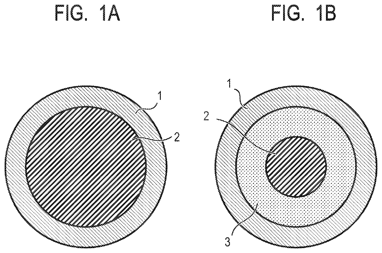
The developing member has an electroconductive substrate, and an elastic layer having a mono-layer structure on the substrate as a surface layer, wherein the elastic layer has a thickness of T μm and a volume resistivity of 1.0×10⁵ Ω·cm to 1.0×10¹² Ω·cm, and includes a first resin as a main binder; and the elastic layer further includes a second resin having a structural unit represented by Formula (1), in a region extending toward a first surface from a second surface by a depth of t μm, where the first surface is defined as a surface of the elastic layer on a side facing the substrate, and the second surface is defined as a surface thereof opposite to the first surface, wherein in the region, a concentration of ether bonds is higher on the second surface side than on the first surface side (provided that T>t):

Description

BACKGROUND OF THE INVENTIONField of the Invention[0001]The present disclosure relates to a developing member incorporated in an apparatus employing an electrophotographic system. The present disclosure also relates to a process cartridge and an electrophotographic image forming apparatus that have the developing member.Description of the Related Art[0002]Japanese Patent Application Laid-Open No. 2009-237358 discloses, in Example 5 and Example 6, an electroconductive roller for electrophotographic equipment, which includes: a shaft body; a base layer formed on an outer circumference of the shaft body and including electroconductive carbon black and silicone rubber; and a surface layer formed on the base layer, wherein the surface layer is formed of a cured product of a resin composition that contains polytetramethylene glycol diglycidyl ether as a main component and a cationic photopolymerization initiator.[0003]The present inventors have investigated the case where the electroconduc...

Claims


Application Information

Patent Timeline
Patent Type & Authority Applications(United States)
IPC IPC(8): G03G15/08G03G21/18
CPCG03G21/1803G03G15/0818G03G15/0808G03G2215/0861
Inventor MORIAI, WATARUNAKAMURA, MINORUISHII, TORUISHIDA, KAZUTOSHI
Owner CANON KK
Learn More