Method and system for compensating offset of resolver

a resolver and offset compensation technology, applied in the direction of electric programme control, dynamo-electric gear control, dynamo-electric converter control, etc., can solve the problem of inability to accurately recognize the output signal of the resolver, the offset compensation may not be appropriately performed, and the absolute position cannot be accurately measured. problem, to achieve the effect of preventing synchronization of a sampling point of time, minimizing the distortion of the output of the resolver, and improving the offset compensation accuracy

Active Publication Date: 2020-05-28
HYUNDAI MOTOR CO LTD +1
View PDF3 Cites 3 Cited by
  • Summary
  • Abstract
  • Description
  • Claims
  • Application Information

AI Technical Summary

Benefits of technology

[0010]Various aspects of the present invention are directed to providing a method and a system for compensating an offset of a resolver, which are configured for improving accuracy of a resolver offset compensation by preventing synchroni

Problems solved by technology

Meanwhile, owing to various causes such as assembly tolerance between the resolver and the motor, inaccuracy in a position of an internal coil of the resolver, and the like, an offset occurs in the output of the resolver such that it is impossible to accurately measure an absolute position due to such an offset.
However, owing to various causes, noise occurs in the output signal of the resolver and information on the output signal of the resolver is not accurately recognized such that a resolver offset compensation may not be appropriately performed.
When a large amount of noise is introduced at a point of time of sampling an output signal of the resolver, the output signal of the resolver is not accurately recognized.
However, when a point of time at

Method used


Image

  • Method and system for compensating offset of resolver
  • Method and system for compensating offset of resolver
  • Method and system for compensating offset of resolver

Examples


Embodiment Construction

[0033]Reference will now be made in detail to various embodiments of the present invention(s), examples of which are illustrated in the accompanying drawings and described below. While the present invention(s) will be described in conjunction with exemplary embodiments of the present invention, it will be understood that the present description is not intended to limit the present invention(s) to those exemplary embodiments. On the other hand, the present invention(s) is / are intended to cover not only the exemplary embodiments of the present invention, but also various alternatives, modifications, equivalents and other embodiments, which may be included within the spirit and scope of the present invention as defined by the appended claims.

[0034]Hereinafter, a method and a system for compensating an offset of a resolver according to various embodiments of the present invention will be described in more detail with reference to the accompanying drawings.

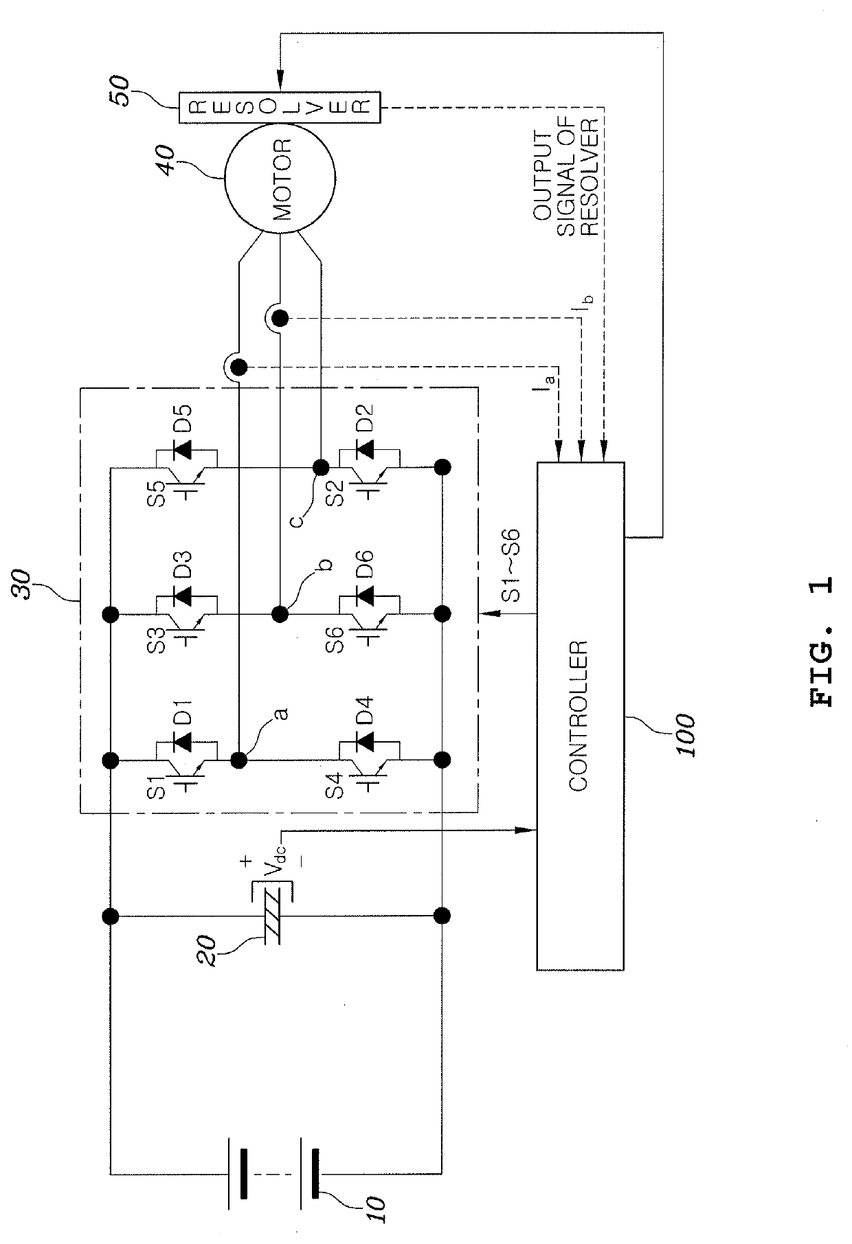
[0035]FIG. 1 is a block diagram...


PUM


Abstract

A method and a system for compensating an offset of a resolver, may include sampling an output signal of the resolver at a predetermined sampling frequency, comparing magnitudes of the sampled output signals of the resolver, when a difference in magnitude between the sampled output signals of the resolver is greater than a predetermined reference value, controlling the motor by a random pulse width modulation (RPWM) scheme in which switching frequencies of the switching elements in the inverter are arbitrarily changed, and compensating an offset of the resolver coupled to the motor while controlling the motor with the RPWM scheme.

Description

CROSS REFERENCE TO RELATED APPLICATION[0001]The present application claims priority of Korean Patent Application No. 10-2018-0145706 filed on Nov. 22, 2018, the entire contents of which is incorporated herein for all purposes by this reference.BACKGROUND OF THE INVENTIONField of the Invention[0002]The present invention relates to a method and a system for compensating an offset of a resolver, and more particularly, to a method and a system for compensating an offset of a resolver, which are capable of improving accuracy of a resolver offset compensation by preventing synchronization of a sampling point of time for an output of a resolver with a switching point of time for an inverter providing a driving current to a motor, thereby minimizing distortion in the output of the resolver at the sampling point of time.Description of Related Art[0003]A motor control unit (MCU) is used to control a motor such as a synchronous motor or an induction motor used in an electric vehicle or a hybri...

Claims


Application Information

Patent Timeline
IPC IPC(8): G05B19/4105H02P21/18H02P21/22H02P27/12H02K24/00
CPCH02P21/18H02P21/22H02P27/12G05B19/4105G05B2219/41065H02K24/00H02P6/16H02P2203/00G01D18/001
Inventor LIM, JAE SANGPARK, JOO YOUNGKANG, GU BAEKIM, YOUNG UN
Owner HYUNDAI MOTOR CO LTD
Why Eureka
Try Eureka