
Method and device for real-time compensation of roll angle deviation of airborne laser radar

An airborne lidar, real-time compensation technology, applied in the direction of measurement device, use of re-radiation, electromagnetic wave re-radiation, etc., can solve the problems of real-time compensation of rolling angle deviation of unloadable platform, and achieve high control speed and high-precision real-time compensation. , the effect of high compensation accuracy

Inactive Publication Date: 2010-12-01
BEIHANG UNIV
View PDF2 Cites 23 Cited by
  • Summary
  • Abstract
  • Description
  • Claims
  • Application Information

AI Technical Summary

Problems solved by technology

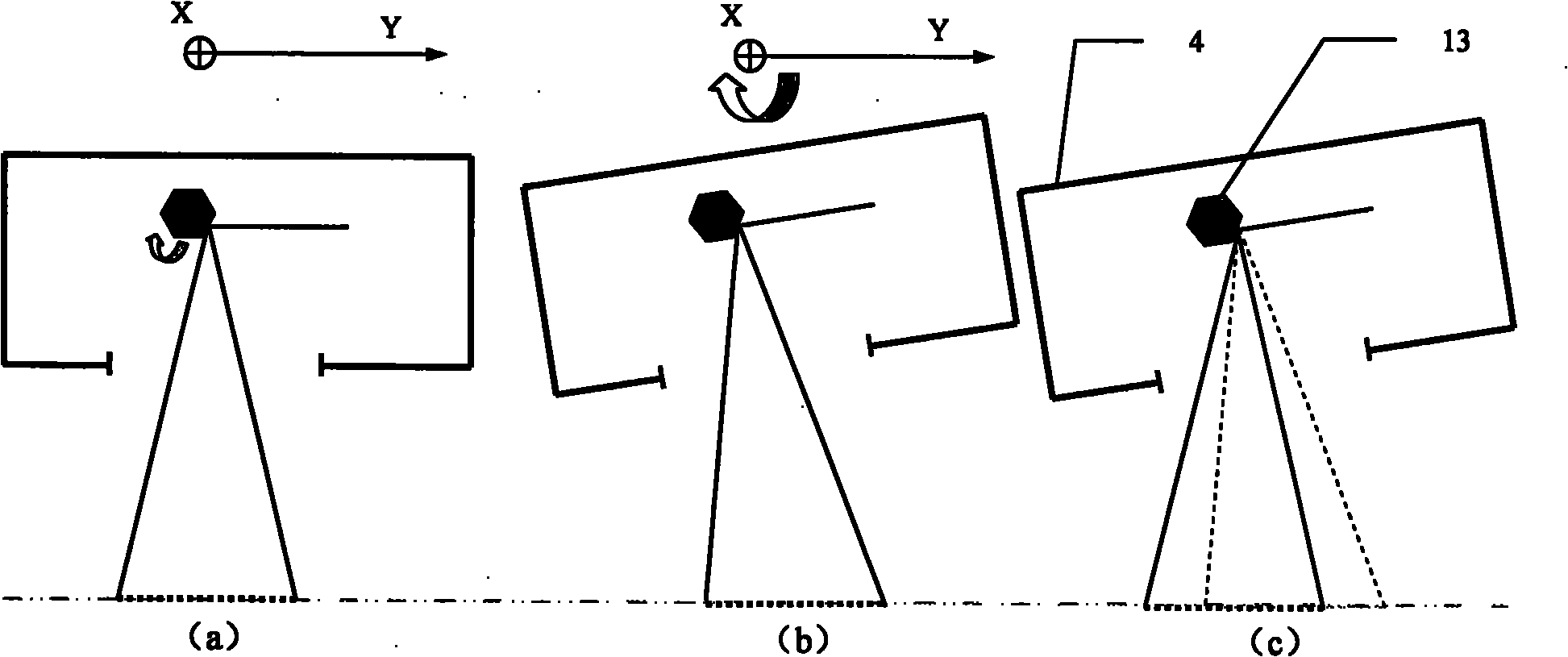
And because the rotating prism rotates at a constant speed, the translation control of the laser periodic pulse sequence in the time interval is equivalent to the translation control of the effective scanning angle interval of the laser periodic pulse sequence on each scanning surface of the multi-faceted rotating prism, so as to realize the rolling angle deviation The purpose of compensation is to solve the problem that the existing airborne laser radar cannot compensate the load platform roll angle deviation in real time

Method used


Image

  • Method and device for real-time compensation of roll angle deviation of airborne laser radar
  • Method and device for real-time compensation of roll angle deviation of airborne laser radar
  • Method and device for real-time compensation of roll angle deviation of airborne laser radar

Examples


Embodiment Construction

[0018] The patent embodiments of the present invention will be further described in detail below in conjunction with the accompanying drawings.

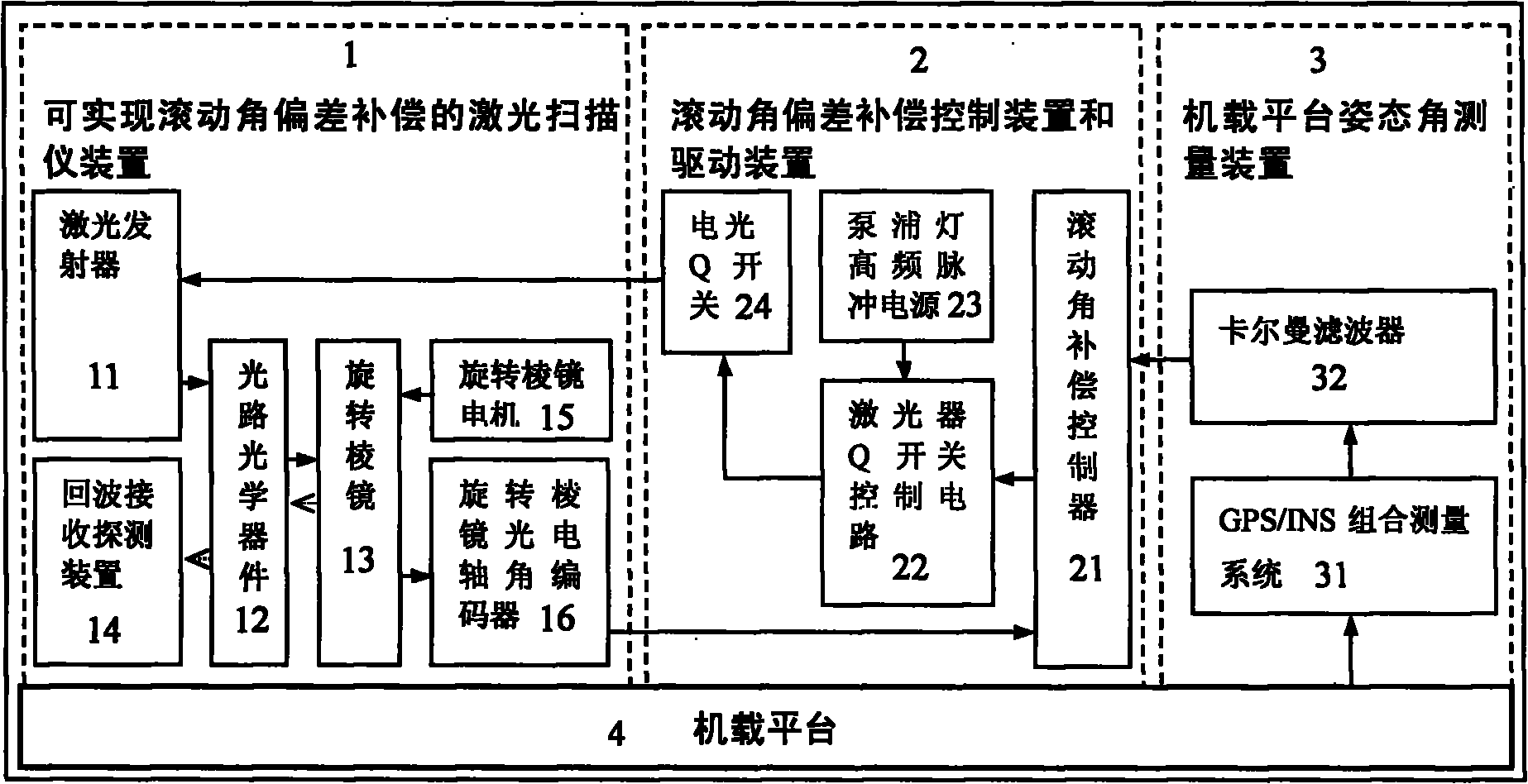
[0019] figure 1 It is a schematic diagram of a method and device for real-time compensation of roll angle deviation of airborne laser radar. During actual flight, due to the interference of various internal and external factors, the airborne platform (4) cannot maintain an ideal uniform linear motion state and a constant attitude angle state (ideal roll angle and pitch angle are zero, yaw Angle is a constant), resulting in attitude angle deviation (including roll angle, pitch angle and yaw angle deviation). Obtain the attitude angle measurement data of the airborne platform (4) by the GPS / INS combined measurement system (31), obtain a high-precision roll angle deviation value through the subsequent processing of the Kalman filter (32), and send it into In the roll angle compensation controller (21). Obtain the real-time rotation a...


PUM


Abstract

The invention discloses a method and a device for the real-time compensation of the roll angle deviation of an airborne laser radar. A roll angle compensation control device and a roll angle driving device are designed mainly. The devices comprise a roll angle compensation controller, a laser Q switch control circuit, a pumping lamp high-frequency pulse power supply and an electro-optic Q switch.The roll angle compensation controller receives the roll angle deviation measured by a GPS / INS combined measuring system, combines a real-time angle measured by a rotary prism optical electric axial angle encoder for making a judgment and outputs a high-level conduction control signal; the signal and a high-frequency pulse signal of the pumping lamp power supply commonly act on the laser Q switchcontrol circuit so that the laser Q switch control circuit outputs the high-voltage pulse signal to the electro-optic Q switch in a control signal connection period so as to control a laser emitter to emit laser pulses in a proper scanning angle area to realize real-time high-precision compensation of the roll angle deviation.

Description

technical field [0001] The invention relates to the problem of compensating roll angle deviations of point-scanning three-dimensional imaging airborne laser radars, in particular to a method and device for real-time compensation of roll angle deviations of airborne laser radars. Background technique [0002] Airborne lidar is a terrain mapping technology based on the principle of laser ranging, which integrates aircraft platforms, laser scanners, differential global positioning system DGPS (Differential Global Positioning System), inertial navigation system INS (Initial Navigation System) and computer data acquisition and processing system, etc. [0003] The working process of the airborne laser radar is as follows: the aircraft flies in a straight line at a constant speed on a pre-set flight route, and the DGPS / INS combined measurement system uses Kalman filter technology to measure the track and attitude angle of the laser scanner payload platform in real time. Calculate ...

Claims


Application Information

Patent Timeline
Patent Type & Authority Applications(China)
IPC IPC(8): G01S7/481G01S17/89
Inventor 徐立军王建军李小路田祥瑞
Owner BEIHANG UNIV
Learn More