Composite cable

a technology of composite cables and connectors, applied in the direction of coaxial cables/analogue cables, cables, basic electric elements, etc., can solve the problems of signal wire deformation and transmission properties deterioration, and achieve the effect of small diameter and resistan

Active Publication Date: 2020-05-28
HITACHI METALS LTD
View PDF0 Cites 0 Cited by
  • Summary
  • Abstract
  • Description
  • Claims
  • Application Information

AI Technical Summary

Benefits of technology

[0014]According to the present invention, it is possible to provide the composite cable, which is small in diamete

Problems solved by technology

In addition, in the composite cable designed to use a communication wire designed for data communication and the like as its signal wire to carry out a high speed signal transmission, deterioration in transmission properties occurs due to a deformation of that signal wire caused by an

Method used


Image

  • Composite cable

Examples


embodiment

[0016]An embodiment of the present invention will be described below in conjunction with the accompanying drawing.

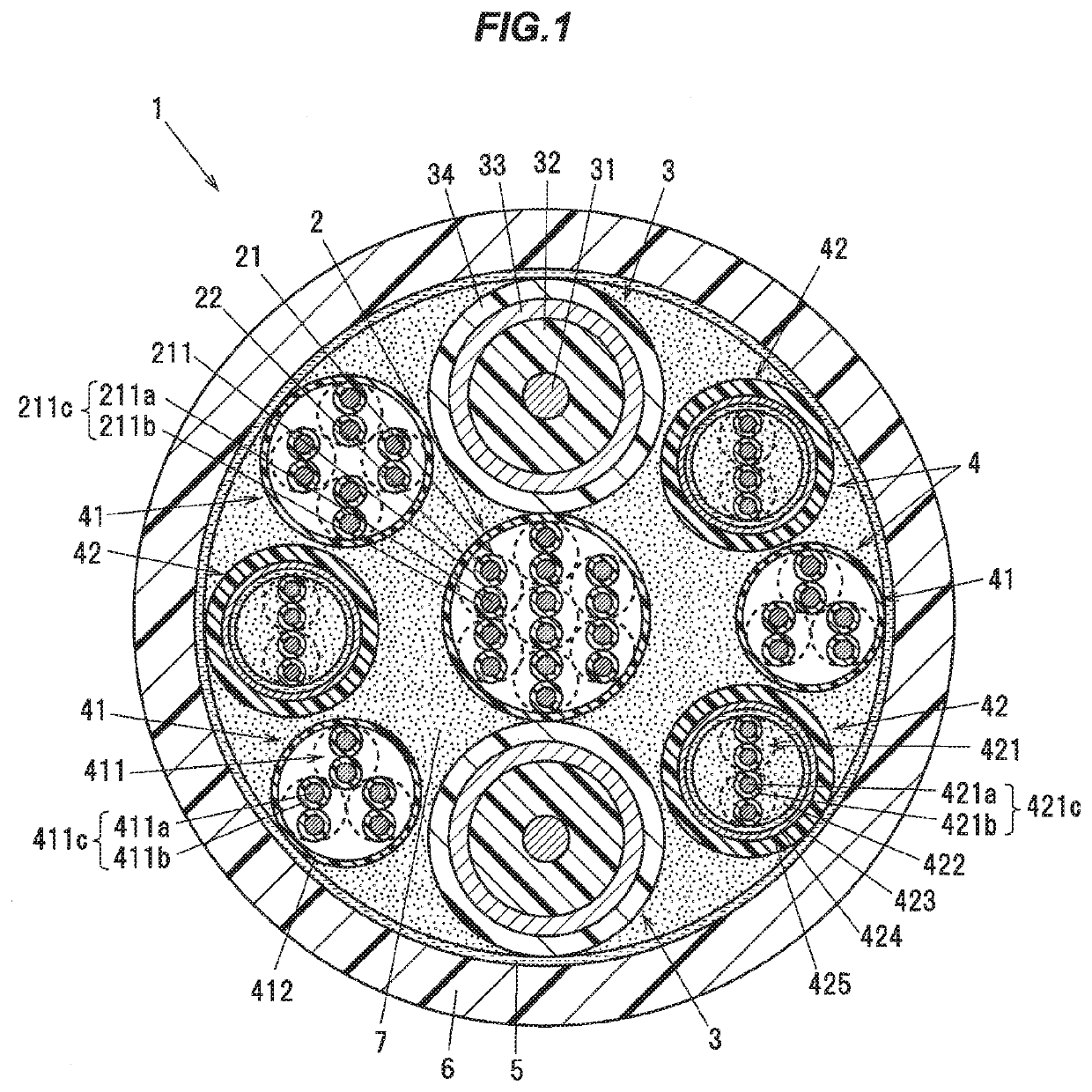
[0017]FIG. 1 is a cross-sectional view showing a cross section perpendicular to a longitudinal direction of a composite cable according to the present embodiment. The composite cable 1 is being designed to be used as a wiring to monitor a motion condition of an industrial robot or a medical robot such as a robot arm and the like, with an image or a video, for example.

[0018]As shown in FIG. 1, the composite cable 1 is being configured to include a power wire 2, a plurality of coaxial wires 3, and a plurality of signal wires 4, which are each smaller in outer diameter than the power wire 2 and the plurality of coaxial wires 3. The power wire 2 is shown as one aspect of a power supply wire of the present invention. Further, the composite cable 1 has an outer diameter of on the order of e.g. 17 mm to 19 mm.

[0019]The power wire 2 is being configured to include a twisted wire ...


PUM


Abstract

A composite cable is composed of a power supply wire, which includes a twisted wire pair aggregate, which are being formed by laying a plurality of twisted wire pairs together, a plurality of coaxial wires, and a plurality of signal wires, which are each smaller in outer diameter than the power supply wire and the plurality of coaxial wires. The plurality of coaxial wires and the plurality of signal wires are being laid helically over an outer periphery of the power supply wire, and each of the plurality of coaxial wires is being arranged in contact with an outer periphery of the power supply wire, and is being arranged at equally spaced intervals in a circumferential direction of the power supply wire, while each of the plurality of signal wires is being arranged in such a manner as to remain separate from the power supply wire.

Description

CROSS-REFERENCE TO RELATED APPLICATION[0001]The present invention is based on Japanese Patent Application No. 2018-220053 filed on Nov. 26, 2018, the entire contents of which are incorporated herein by reference.BACKGROUND OF THE INVENTION1. Field of the Invention[0002]The present invention relates to a composite cable.2. Description of the Related Art[0003]As a composite cable to be used in indoor wiring, there is known a composite cable, which includes a coaxial wire and a signal wire being laid together therein, for example (see JP-A-2000-123648, for example).[0004][Patent Document 1] JP-A-2000-123648SUMMARY OF THE INVENTION[0005]In recent years, with increasing amount of information in communication between devices and with increasing communication speed therefor, the number of electric wires or cables of each type to be built into the composite cable is being increased, which leads to an increase in outer diameter of the entire composite cable as well. However, a decrease in si...

Claims


Application Information

Patent Timeline
IPC IPC(8): H01B11/18H01B11/04H01B11/20
CPCH01B11/20H01B11/1895H01B11/04H01B11/1891
Inventor HUANG, DETIANTSUKAMOTO, YOSHINORIKOBAYASHI, MASANORIMATSUOKA, ISAOMORIYAMA, MASASHI
Owner HITACHI METALS LTD
Why Eureka
Try Eureka