
Spatial Scalable Video Coding

a video coding and spatial scaling technology, applied in the field of spatial scaling video coding, can solve the problems of high memory consumption, high implementation complexity of multi-loop video coding design such as shvc, and delays when a user is present, so as to reduce artefacts, increase compression efficiency, and fast processing

Active Publication Date: 2020-05-28
KONINK KPN NV +1
View PDF0 Cites 2 Cited by
  • Summary
  • Abstract
  • Description
  • Claims
  • Application Information

AI Technical Summary

Benefits of technology

The coding schemes described in this patent provide a way to create video content that can be played on different devices with different resolutions. This is accomplished by using lower resolution components that have the same spatial resolution as the video content, which eliminates the need for different buffer settings for each resolution layer. The coding scheme is designed to be efficient and easy to implement, making it suitable for use in existing coding standards or as a pre-processing and post-processing step in a new coding standard. The main technical effect of this invention is to provide a flexible and scalable video coding system with low implementation costs.

Problems solved by technology

Due to the decoding dependency of the enhancement layer, a delay is introduced in the decoding scheme that scales with the amount of enhancement layers.
This design has the same disadvantage in the sense that due to the decoding dependencies between the base layer and enhancement layers multiple decoding loops (2 or more when there are more than one enhancement layers) have to be sequentially processed.
This results in delays when a user wants to switch to a higher resolution, or when tuning in a broadcast stream where decoder needs to first decode the base layer and then the enhancement layers.
More generally, a multi-loop video coding design such as SHVC introduces a high implementation complexity and high memory consumption since the decoder needs to store the decoded frames in memory (as long as they are needed for decoding dependant frames from enhancement layers).
The complexity makes codec designs such as SHVC make less attractive for fast development of a hardware implementation that is required for industry acceptance.

Method used


Image

  • Spatial Scalable Video Coding
  • Spatial Scalable Video Coding
  • Spatial Scalable Video Coding

Examples


Embodiment Construction

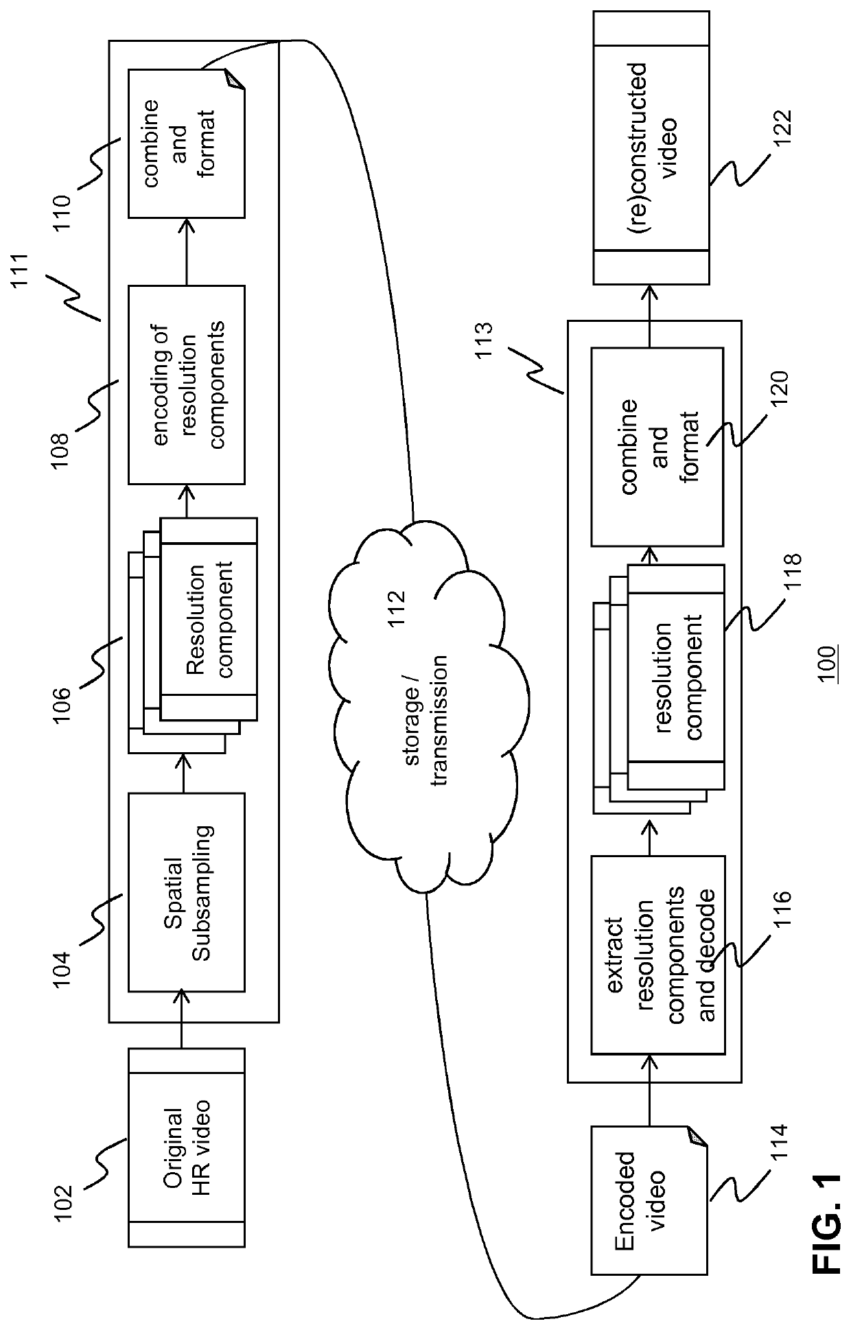
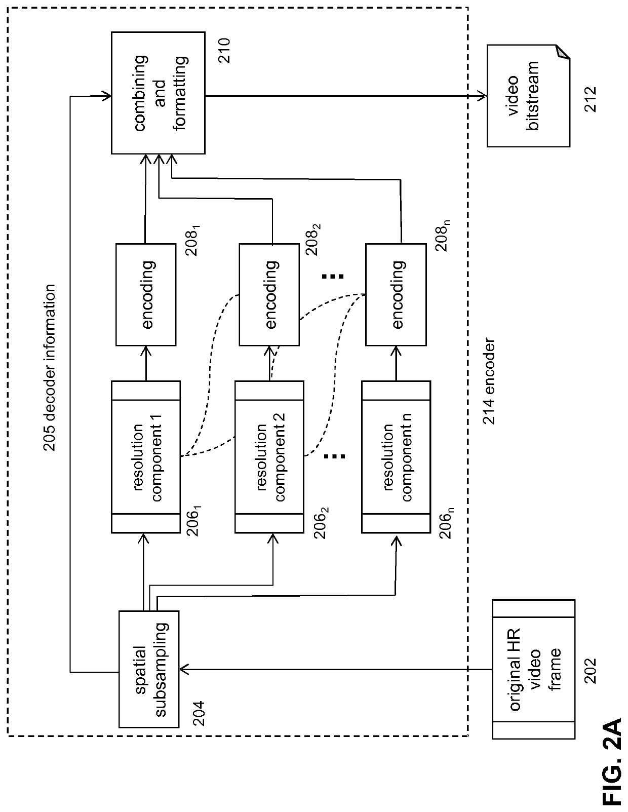
[0075]FIG. 1 depicts a schematic of the coding system according to an embodiment of the invention. In particular, FIG. 1 depicts a coding system comprising an encoding device 111 and an associated decoding device 113. The encoding device may be implemented as a network encoder configured to receive multiple LR video signals of the same or substantially the same scene. In an embodiment, the multiple LR video signals (LR descriptions) may be generated on the basis of a HR video signal 102. For example, in an embodiment, a spatial subsampling technique 104, such as a polyphase subsampling technique, may be used in order to generate multiple LR descriptions 106 on the basis of the HR video signal. Each of the LR descriptions may then be encoded into multiple encoded LR descriptions.

[0076]The LR descriptions may be encoded on the basis of a predetermined coding standard, e.g. AVC, HEVC, VP9, etc. Further, at least one of the LR descriptions is encoded such that it can be independently de...


PUM


Abstract

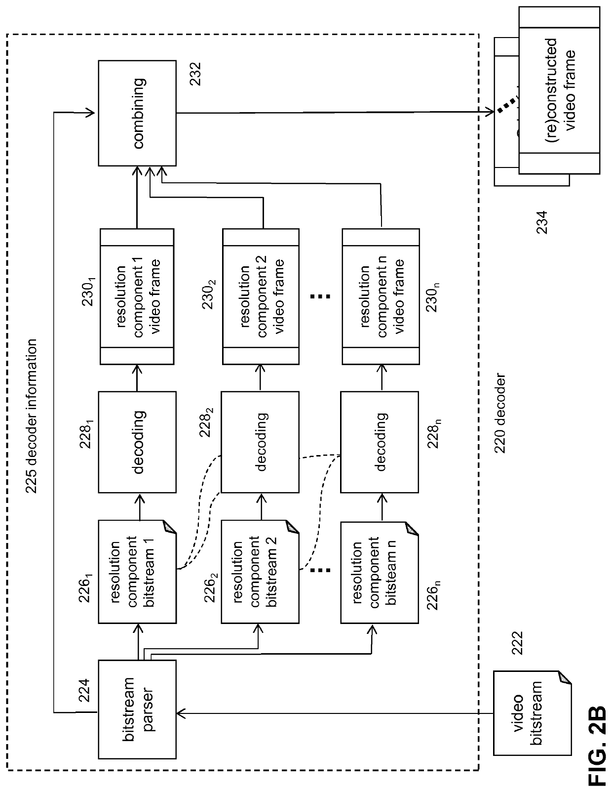
A method of forming a video signal by a decoder device is described wherein the method comprises receiving a bit-stream and decoder information, the decoder information signaling the decoder device the presence of one or more resolution components in the bitstream for forming a video signal, a resolution component representing a spatially subsampled version, preferably a polyphase subsampled version, of a first video signal having a first resolution, the one or more resolution components being part of a resolution component group, the group comprising a plurality of resolution components on the basis of which the first video signal is reconstructable; and, the decoder device parsing the bitstream and decoding the one or more resolution components into video frames on the basis of the decoder information.

Description

FIELD OF THE INVENTION[0001]The invention relates to spatial scalable video coding, and, in particular, though not exclusively, to methods and systems for spatial scalable video coding, a decoder device adapted for decoding encoded video that is spatially scalable and an encoder device for encoding video into spatial scalable video data and a computer program product for executing such methods.BACKGROUND OF THE INVENTION[0002]Currently a video coding standard known as the high-efficiently video coding (HEVC or ITU-T H.265) has been developed which may provide a substantially higher compression efficiency when compared to other coding standards such as H.264 / AVC (MPEG-4 part 10 Advance Video Coding). Additionally, the scalable extensions of HEVC (SHVC) provides a layered HEVC-based video coding scheme that is comparable to the scalable video coding standard SVC that is based on a base layer and enhancement layers. In such scheme a decoder decodes the base layer, generates the output ...

Claims


Application Information

Patent Timeline
Patent Type & Authority Applications(United States)
IPC IPC(8): H04N19/59H04N19/33H04N19/436H04N19/184
CPCH04N19/184H04N19/436H04N19/33H04N19/59H04N19/39
Inventor THOMAS, EMMANUELNIAMUT, OMAR AZIZKOENEN, ROBERT
Owner KONINK KPN NV
Learn More