
Medical image modeling system and medical image modeling method

a medical image and modeling system technology, applied in the field of image modeling system, can solve the problems of inconvenient bone reconstruction model production, patient may experience face deformation or even loss of speech, chewing or swallowing ability, oral function, appearance, mental health of patients, etc., and achieve favorable bone reconstruction model editing effect, convenient and quick bone model editing

Active Publication Date: 2020-06-04
METAL INDS RES & DEV CENT
View PDF0 Cites 0 Cited by
  • Summary
  • Abstract
  • Description
  • Claims
  • Application Information

AI Technical Summary

Benefits of technology

The invention is a medical image modeling system and method that allows for quick and easy editing of bones using a bone reconstruction block. This system provides a convenient way to create a favorable bone reconstruction model. Overall, the invention enables quick and effective modeling of bones using a user-friendly interface.

Problems solved by technology

The patient may experience face deformation or even loses the ability to speak, chew or swallow, and oral function, appearance, and mental health of the patient may be seriously affected as well.
For this reason, production of the conventional artificial bone repair model involves a complex process of image file format conversion, which is rather inconvenient for producing the repair model.
Therefore, how to provide a fast and convenient modeling system is an important issue, and several solutions and implementations are thus provided as follows.

Method used


Image

  • Medical image modeling system and medical image modeling method
  • Medical image modeling system and medical image modeling method
  • Medical image modeling system and medical image modeling method

Examples


Embodiment Construction

[0027]The term “couple” used throughout this specification (including the claims) may refer to any direct or indirect connection means. For example, if it is described that the first device is coupled to the second device, it should be understood that the first device may be directly connected to the second device or indirectly connected to the second device through other devices, wires, or certain connection means. Moreover, elements / components / steps with the same reference numerals represent the same or similar parts in the figures and embodiments where appropriate. Descriptions of the elements / components / steps with the same reference numerals or terms in different embodiments may be references for one another.

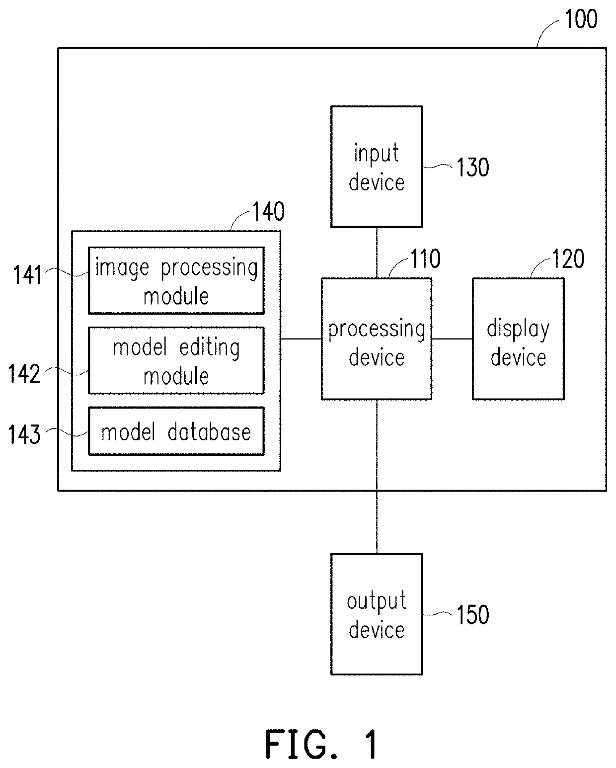
[0028]FIG. 1 is a schematic view of a medical image modeling system according to an embodiment of the invention. With reference to FIG. 1, a medical image modeling system 100 includes a processing device 110, a display device, 120, an input device 130, and a storage device 1...


PUM


Abstract

A medical image modeling system and a medical image modeling method are provided. The medical image modeling system includes an input device, a processing device, and a storage device. The input device obtains medical image data. The processing device is coupled to the input device. The processing device converts the medical image data into a bone model in response to a first operational command. The storage device is coupled to the processing device. The storage device stores a model database. The processing device reads the model database in response to a second operational command to obtain a bone reconstruction block corresponding to a defect block of the bone model. The processing device integrates a bone reconstruction model depicted corresponding to the bone reconstruction block into the defect block of the bone model to generate an integrated bone model.

Description

TECHNICAL FIELD[0001]The invention relates to an image modeling technique. More particularly, the invention relates to a medical image modeling system and a medical image modeling method.DESCRIPTION OF RELATED ART[0002]In the treatment for bone repair, it is common to use an artificial bone repair model to restore bone defects in bone repair surgery. Common oral bone defects are caused by car accident injuries, infection, and cancer and tumor most of the time. The patient may experience face deformation or even loses the ability to speak, chew or swallow, and oral function, appearance, and mental health of the patient may be seriously affected as well. Nevertheless, the conventional artificial bone repair model is made by using medical image software to read a medical image of the bone tissue and then using conversion software to convert the medical image into a stereoscopic bone image. For this reason, production of the conventional artificial bone repair model involves a complex p...

Claims


Application Information

Patent Timeline
Patent Type & Authority Applications(United States)
IPC IPC(8): G06T19/20G06T17/00G06T7/60G06F3/0481G06F3/0482G16H30/40
CPCG06T19/20G06T2200/24G06T2219/2004G06T2207/20092G06F3/0482G16H30/40G06F3/04817G06T2207/30008G06T7/60G06T17/00G16H50/50G16H20/40G06F3/04815G06T2200/04G06T2207/10081G06T7/0012G06T2207/10088G06T2207/30036G06T2207/30052G06T5/77
Inventor LO, KAI-SZUTZENG, JIAN-JIAYANG, SHENG-HONGPAN, BO-WEI
Owner METAL INDS RES & DEV CENT
Learn More