

Waveguide unit, waveguide device, and connection method
a technology of waveguide and processing unit, which is applied in the direction of waveguide type devices, transmission, basic electric elements, etc., can solve the problems of poor flexibility and efficiency of the waveguide device disclosed in the patent literature 1 described above, and achieve the effect of reducing loss and delay, and improving flexibility and efficiency of adding a transmission/reception processing uni
- Summary
- Abstract
- Description
- Claims
- Application Information
AI Technical Summary
Benefits of technology
Problems solved by technology
Method used
Image

Examples
first example embodiment
[0030]
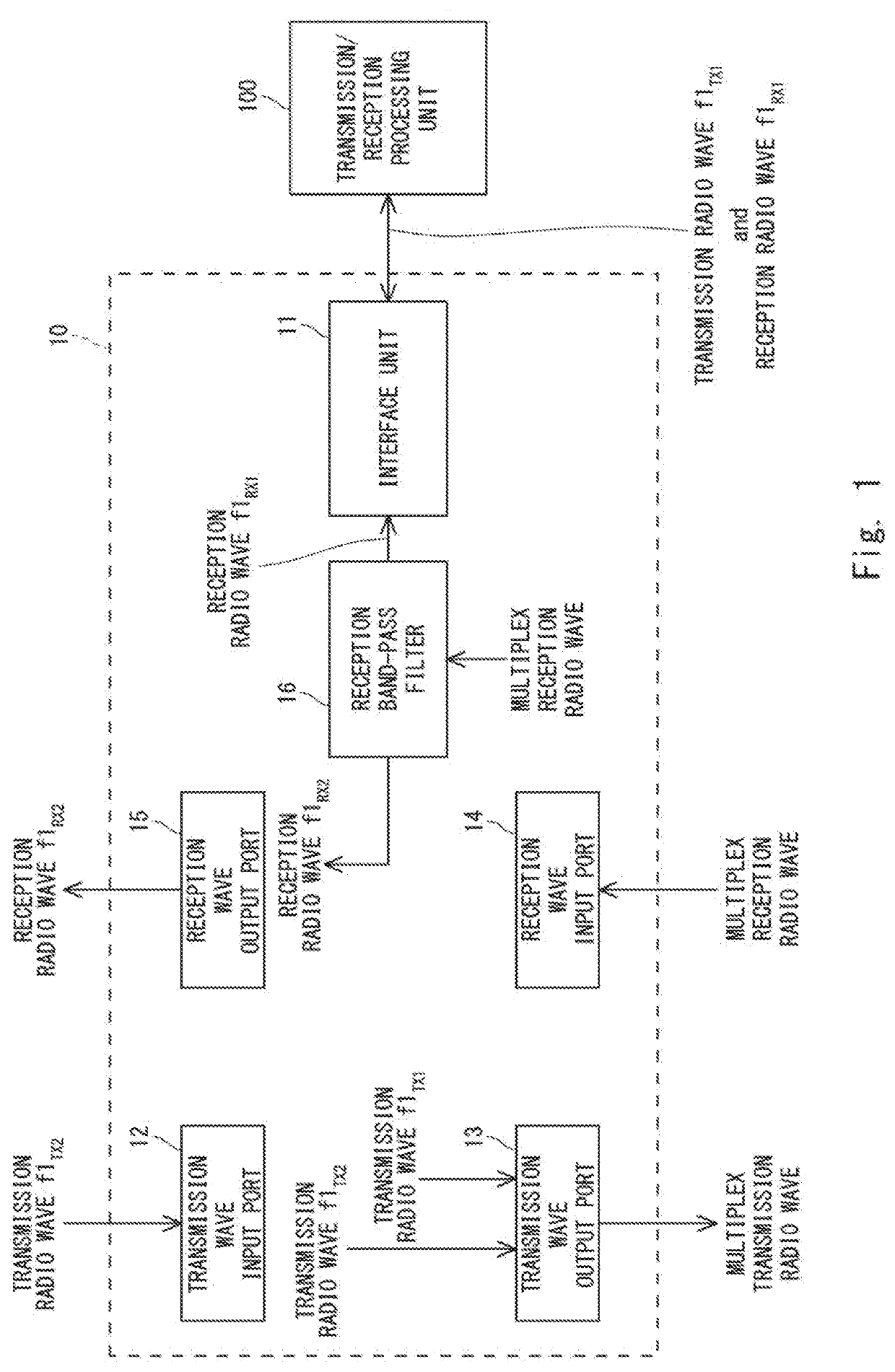
[0031]FIG. 1 is a diagram illustrating one example of a waveguide unit according to a first example embodiment. A waveguide unit 10 illustrated in FIG. 1 is configured to be connectable to each of a transmission / reception processing unit 100 being a “first connected object unit”, a second connected object unit (not illustrated), and a third connected object unit (not illustrated). Hereinafter, description is given on the assumption that the third connection unit is another waveguide unit. Then, the third connection unit is configured to be connectable to another transmission / reception processing unit having a transmission frequency and a reception frequency different from those of the transmission / reception processing unit 100, and has the same configuration as that of the waveguide unit 10.
[0032]In FIG. 1, the waveguide unit 10 includes an interface unit (first interface unit) 11, a transmission wave input port (first transmission wave input port) 12, a transmission wave outp...
second example embodiment
[0040]A second example embodiment relates to a more specific configuration of a waveguide unit as compared with the first example embodiment.
[0041]
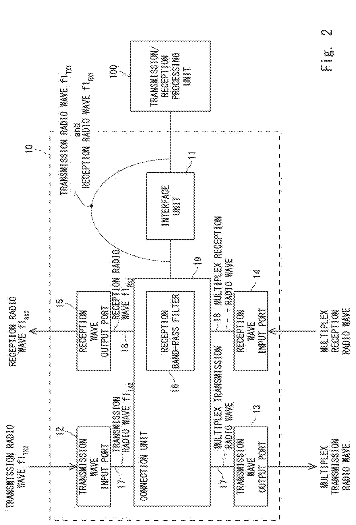
[0042]FIG. 2 is a diagram illustrating one example of the waveguide unit according to the second example embodiment. In FIG. 2, a waveguide unit 10 according to the second example embodiment further includes a waveguide (first waveguide, transmission wave waveguide) 17, a waveguide (second waveguide, reception wave waveguide) 18, and a connection unit 19. The waveguide 17 and the waveguide 18 are disposed away from each other. In other words, the waveguide 17 and the waveguide 18 are separated from each other.
[0043]The waveguide 17 connects a transmission wave input port 12 to a transmission wave output port 13 via the connection unit 19. Further, the waveguide 18 connects a reception wave input port 14 to a reception wave output port 15 via the connection unit 19.
[0044]The connection unit 19 is interposed between the transmission wave in...
third example embodiment
[0047]A third example embodiment relates to a more specific configuration of a waveguide unit. Further, the third example embodiment relates to a waveguide device including the waveguide unit and a transmission / reception device including the waveguide device.
[0048]
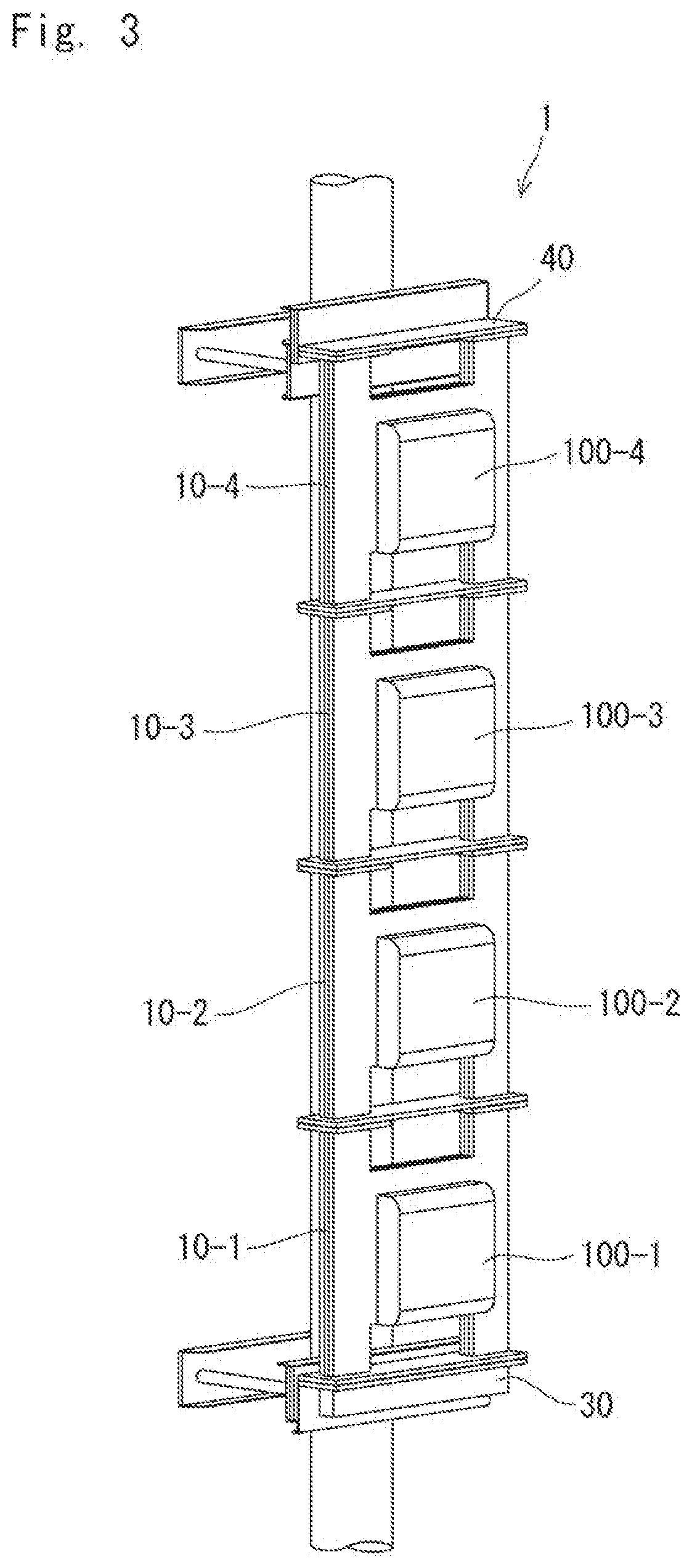
[0049]FIG. 3 is a diagram illustrating an external configuration example of a transmission / reception device including a waveguide device and a transmission / reception processing unit connected to the waveguide device according to the third example embodiment. FIG. 4 is a diagram illustrating one example of an internal configuration of the transmission / reception device including the waveguide device and the transmission / reception processing unit connected to the waveguide device according to the third example embodiment. The transmission / reception device illustrated in FIGS. 3 and 4 is, for example, an outdoor installation-type transmission / reception device. FIG. 3 illustrates a state where the transmission / reception device ...
PUM
 Abstract
Description
Claims
Application Information