Method for environmental analysis and control of spatial areas

a spatial area and environmental analysis technology, applied in the field of spatial area environmental analysis and control, can solve the problems of absolute and fixed number, not “smart", etc., and achieve the effect of facilitating bidirectional communication with the user, enhancing thermal analysis, and acceptable thermal control level

Active Publication Date: 2020-06-11
HUNKA ROBERT STEPHEN
View PDF12 Cites 0 Cited by
  • Summary
  • Abstract
  • Description
  • Claims
  • Application Information

AI Technical Summary

Benefits of technology

[0002]The goal of the MET HOD FOR ENVIRONMENTAL ANALYSIS AND CONTROL OF SPATIAL AREAS as a continuation based on the Spatial Environmental Control Unit (USPTO application Ser. No. 15 / 979,204) is to create a user friendly accurate analysis of heat transfer dynamics in one or more spatial areas that is responsive to the thermal dynamics of the area of interest and accurate to maintain an acceptable level of thermal control as environmental and biological human conditions change without requiring excessive interruptions to the user for manual adjustment. The method developed with the Spatial Environmental Control Unit (Ser. No. 15 / 979,204) makes the current norm of an “absolute” temperature control approach for thermal control and human comfort obsolete. A COMFORT “theory of relativity” will be the new norm. The proposed dynamic method of analyzing the thermal changes rapidly within the area of detection responds to the variable thermal changes in environment better than the best static or “learning” process currently available. Even though the current “learning” process for thermal control makes periodic changes based on logged user preferences as a function of time, it still controls for extended time periods with a single static temperature set point. Basically, a series of a series of static control sequences as a function of time. The proposed MET HOD ENVIRONMENTAL FOR ANALYSIS AND CONTROL OF A SPATIAL AREA incorporates the dynamics of analyzing real time thermal changes with timely feedback from the user.
[0003]The IMPLEMENTATION is as follows:
[0004]The thermal heating or cooling capacity of any object in a space produces infrared energy that can be observed and measured by an infrared radiation detector. At least one multi-spectral multi-pixel infrared sensing detector measures infrared radiation of objects in at least one spatial area and communicates the infrared radiation data to an electronic control unit for analysis wherein each radiation sensing cell or pixel converts the thermal radiation from an object to a change in measurable electrical property (including, but not limited to, a photo-current, a resistance, a voltage) such that the property can be read, transmitted and stored for analysis. That electrical signal is representative of the radiation level and heating or cooling potential of any object on other objects in its line of sight. The resolution of the electrical signal map from the pixels within the array will allow determination of the nature of the thermal load and heat transfer between objects in the area of detection. The resolution is a function of the number of pixels and the ability of the lens to focus the radiation and the accuracy of the infrared radiation detecting pixels. The current “obsolete” state of art using infrared sensors in environment thermal control, at best, averages some or all of the electrical signals from the infrared pixels. This is better than a single point non-infrared temperature sensor or multiple temperature sensors because, with current infrared sensors, each pixel is a sensor that supports the averaging and subsequent post processing to determine a temperature that represents the average temperature of object in the area of detection. But this approach continues the “obsolete” approach of temperature as an single absolute measurement of thermal level. The proposed method looks at the spatial dynamics, in 2D and 3D, to better define the heat transfer between objects in the area of detection and the movement of the thermally conditioned fluid. Natural light visibility imaging, incorporated in the proposed method, enhances thermal analysis and facilitates bidirectional communication with the user. Additionally, the resolution of the infrared sensor (pixel count) and the capability to analyze changes in consecutive logged images allow tracking of the conditioned fluid movement within the area of detection based on the consecutive thermal infrared radiation signals used for communication to the electronic control unit. The tracked thermal movement is valuable feedback on the direction and flow rate of the conditioned fluid to determine the effectiveness of the METHOD FOR ENVIRONMENTAL ANALYSIS AND CONTROL OF SPATIAL AREAS.
[0005]Our method will employ a multi-pixel, multi-spectral infrared radiation sensor, a custom algorithm to map the thermal load distribution and the dynamic transfer of heat in the spatial area of interest. The most common applications would be the accurate and timely control of user human comfort in an office, room in a residential space or an outdoor spatial area. Ultra-low power sensing devices is incorporated for remote room temperature, supply air temperature, occupancy detection for control and security, and safety functions of fire and smoke detection.
[0006]The control method is as follows:
[0007]Position and mount an infrared sensor in a location that allows mapping infrared radiation in one or more spatial areas. (Optionally: Using internal angular adjustment capability, direct the infrared and adjust the focus for the required field of view to one or more spatial areas). Map the infrared radiation level from each pixel sensing radiation in one or more spatial areas. (Optionally: Prioritize the approximate location of the focus of interest to apply weighting factors and calculations for objects with the best starting point for determination of ambient thermal load dynamics that affect the thermal requirements.) The thermal load dynamics analysis include calculation of both convective heat transfer within one or more spatial areas and radiation heat transfer directly between objects in one or more spatial areas. Input the heating and cooling capability of the thermally conditioned fluid and location of the source of thermally conditioned fluid.

Problems solved by technology

The drawbacks of a single temperature measurement in space is that the number is an absolute and fixed numerical measurement or calculation.
It applies to point or a single average number within an area and is not “smart” enough to understand the variations in temperature distribution throughout the spatial area of interest and the variables in human perception of comfort in a timely fashion.

Method used


Image

  • Method for environmental analysis and control of spatial areas
  • Method for environmental analysis and control of spatial areas
  • Method for environmental analysis and control of spatial areas

Examples


Embodiment Construction

[0023]While describing the invention and its embodiments, various terms will be used for the sake of clarity. These terms are intended to not only include the recited embodiments, but also all equivalents that perform substantially the same function, in substantially the same manner to achieve the same result.

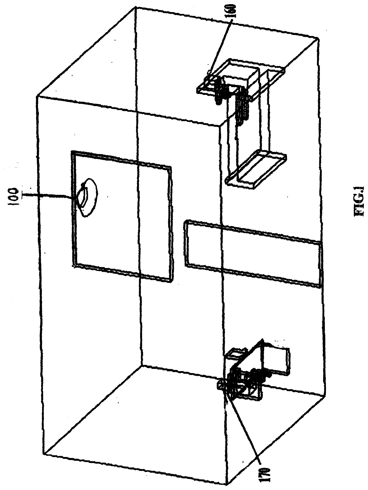
[0024]Now referring to FIG. 1 which discloses a preferred location for a multi-pixel, multi-spectral infrared radiation sensor, positioned in a housing for conditioned fluid flow passage, referenced by numeral 100 scanning infrared radiation in spatial areas. The entire room can be scanned as a single spatial area or sub-divided into smaller spatial areas. Spatial area locations are reference by numerals 160 and 170.

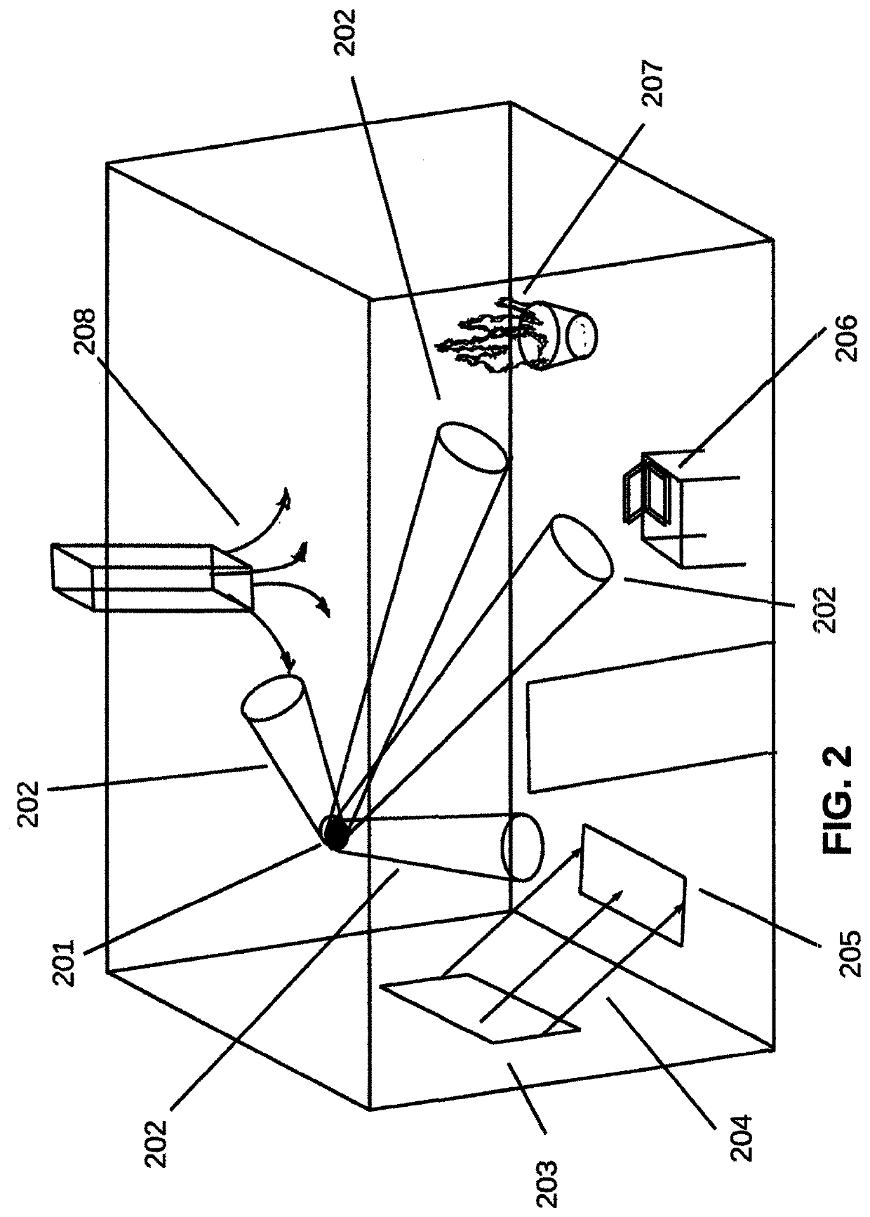
[0025]Now referring to FIG. 2 which discloses a location of a multi-pixel, multi-spectral infrared radiation sensor referenced by numeral 201 positioned on a wall to measure infrared radiation in one or more spatial areas. The infrared radiation sensor is directed t...


PUM


Abstract

The goal of the METHOD FOR ENVIRONMENTAL ANALYSIS AND CONTROL OF SPATIAL AREAS as a continuation of “The Spatial Environmental Control Unit” is a method of logging multi-spectral, multi-pixel infrared radiation data of objects in a spatial area for the analysis and control of heat transfer dynamics in the spatial area that is responsive to feedback for controlling the thermal conditions in the spatial area. The METHOD FOR ENVIRONMENTAL ANALYSIS AND CONTROL OF SPATIAL AREAS further makes the current norm of an “absolute” temperature control approach for thermal control and human comfort obsolete. Ambient environmental conditions and user preference variables makes the current, approach to thermal control time consuming, inaccurate and tedious. The Spatial Environmental Control Unit as one of our foundation patents disclosed the physical components make thermal control and analysis more responsive and user friendly. The METHOD FOR ENVIRONMENTAL ANALYSIS AND CONTROL OF SPATIAL AREAS makes the control and analysis of the thermal properties of the spatial area more intuitive by providing visual images on any compatible device simplifying the understanding of the dynamics of heat transfer in an environment. Tedium and frustration become understanding and empowerment. This method enables gaining knowledge and using tools for analysis, allowing a user to “redesign” his environment by correcting ambient conditions and improving the operation of the thermal conditioning equipment. The end result is a better thermal environment with higher energy efficiency.

Description

BACKGROUND OF THE INVENTION[0001]From the early days of HVAC the focus for conditioning air for human comfort has been based on measuring temperature. From mercury thermometers to thermistors, thermocouples, RTDs, technology has advanced to refine the accuracy of temperature measurement as determined by the air temperature at a single point or averaged over an area in space. The drawbacks of a single temperature measurement in space is that the number is an absolute and fixed numerical measurement or calculation. It applies to point or a single average number within an area and is not “smart” enough to understand the variations in temperature distribution throughout the spatial area of interest and the variables in human perception of comfort in a timely fashion. The acceptability of thermal environmental level varies whether an individual wants conditions warmer or cooler than the current level. If controlling thermal comfort, individuals may prefer warmer temperatures indoors on c...

Claims


Application Information

Patent Timeline
Patent Type & Authority Applications(United States)
IPC IPC(8): G01J5/00
CPCG01J2005/0085G01J2005/0077G01J5/0037G01J5/0859G01J5/047G01J5/025F24F11/89F24F11/63G01J5/068G01J5/485G01J5/064G01J5/48G01J5/80
Inventor HUNKA, ROBERT STEPHEN
Owner HUNKA ROBERT STEPHEN
Why Eureka
Try Eureka