
Hand-off between ultra-wideband cell sites

a cell site and ultra-wideband technology, applied in the field of ultra-wideband communication systems, can solve the problems of large amount of data sent on both wide area and local communication systems, large amount of bandwidth available in traditional communication bands, and large amount of generated pulses, etc., to achieve effective linkage and maintain an acceptable level of service and coverage, and efficiently utilize bandwidth and system resources

Inactive Publication Date: 2005-03-03
INTELLECTUAL VENTURES HOLDING 81 LLC
View PDF31 Cites 26 Cited by
  • Summary
  • Abstract
  • Description
  • Claims
  • Application Information

AI Technical Summary

Benefits of technology

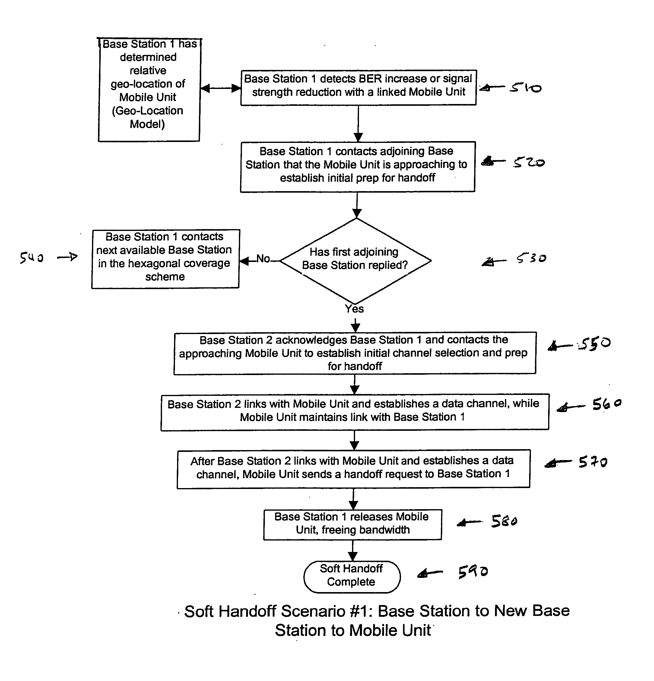
[0012] It is an object of the present invention to provide mobile ultra-wideband methods and devices for effectively linking and maintaining an acceptable level of service and coverage while simultaneously handling multiple data streams and multiple users. It is also an object of the present invention to efficiently utilize bandwidth and system resources. To meet the stated objectives, and to overcome or greatly alleviate the disadvantages in known ultra-wideband units, the present invention provides methods, systems, software and related devices for performing a “soft hand-off” between and within ultra-wideband cells.
[0013] Briefly, the present invention provides a dynamic channel re-assignment capability to mobile units, base stations and sectors within base station coverage areas. The wireless devices may include impulse radio communication devices such as ultra-wideband radio (also known as digital pulse wireless) communication devices. The bandwidth and channel allocation of these devices and sectors can be effectively managed with the present invention despite the fact that link quality generally deteriorates near the outer boundary of the base station. This effective management is achieved by having the mobile unit maintain dual communication with a linked base station and an adjoining base station. The present invention thereby reduces the bit error rate and maintains signal strength (e.g., RF signal strength). This dual communication procedure is termed a “soft-handoff”.
[0015] Advantageously, the present invention efficiently insures that a soft hand-off is performed for a mobile device as it moves from one location to another. This greatly enhances the desirability of the associated ultra-wide band system by minimizing or eliminating interruptions in communication. High quality communication is thus maintained and at the same time the ability to accommodate additional traffic is provided.

Problems solved by technology

The amount of data being sent on both wide area and local communication systems is mushrooming, and it may quickly exceed the bandwidth available in the traditional communication bands.
The generated pulses are so small that they typically exist in the noise floor of other more traditional communication systems.
Ultra-Wideband systems, however, must operate at extremely low power, typically transmitting signals at the noise level.
This high density of antennas may, under some circumstances, lead to cross-talk between the channels assigned to different users.
There are also likely to be other times when that same cell is saturated, thereby causing undesirable drops in transmissions, connection refusals, and quality degradation.
Adding cells and antennas, however, can be a costly and time-consuming process.
Although ultra-wideband technology has the ability to decrease the impact of multipath interference, it is still subject to attenuation of the received signal as the signal passes between transmitter and receiver.
This is due to multipath cancellation, which is present even in ultra-wideband signals.
In either scenario, the attenuation of the signal can decrease the signal level to a value that is unsuitable for reliable data transfer.
Due in part to the deficiencies described above, conventional ultra-wideband communication systems risk poor quality of service, especially as a mobile unit moves from one location to another.
Such systems also do not enable entirely efficient utilization of bandwidth and system resources.

Method used


Image

  • Hand-off between ultra-wideband cell sites
  • Hand-off between ultra-wideband cell sites
  • Hand-off between ultra-wideband cell sites

Examples


Embodiment Construction

[0036] In the following paragraphs, the present inventions will be described in detail by way of example with reference to the attached drawings. Throughout this description, the preferred embodiment and examples shown should be considered as exemplars, rather than as limitations on the present invention. As used herein, “the present invention” refers to any one of the embodiments of the invention described herein.

[0037] I. Soft Hand-Off and Mobile Ultra-Wideband Dynamic Linking Architecture

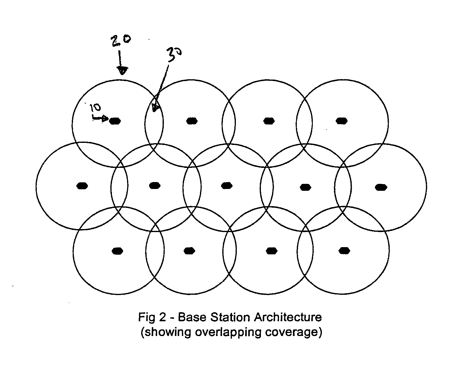
[0038]FIG. 2 illustrates a preferred base station 10 hexagonal topology 100 that will provide overlapping coverage 30 for ultra-wideband base stations 10. Other configurations may also be used, such as a micro pico-network on a daisy chain backbone, placed like emergency call boxes along a highway, for separate routing of signals, but this configuration will allow an effective soft hand-off, which is essential for code-based cellular communications. Base station topologies can be hexagonal or l...


PUM


Abstract

Briefly, the present invention provides a dynamic channel re-assignment capability between mobile units, base stations and sectors within base station coverage areas. The wireless devices used in the present invention may include impulse radio communication devices such as, for example ultra-wideband radio (also known as digital pulse wireless) communication devices. Ultra-wideband bandwidth and channel allocation can be effectively managed, even though link quality generally deteriorates near the outer boundary of the base station. By maintaining dual communications with an adjoining base station, the present invention reduces the bit error rate and maintains signal strength (e.g., RF signal strength). This procedure is termed a “soft-handoff”.

Description

[0001] Priority is claimed from U.S. provisional patent application Ser. No. 60 / 255,469, filed on Dec. 14, 2000, entitled “Ultra-Wideband Communication System and Method”, which is incorporated herein by reference in its entirety.FIELD OF THE INVENTION [0002] The present invention relates to the field of ultra-wideband communication systems. More particularly, the present invention relates to hand-offs between cell sites in an ultra-wideband communication system. BACKGROUND OF THE INVENTION [0003] Wireless communication systems are changing the way people work, entertain, and communicate. For example, portable phones and other mobile devices have enabled highly mobile individuals to easily communicate. Such devices can transmit and receive both voice and data signals. As more features are added to these mobile wireless devices, users are able to receive a wider variety of information. This enhances the user's entertainment and more efficiently solves the user's business problems. [0...

Claims


Application Information

Patent Timeline
Patent Type & Authority Applications(United States)
IPC IPC(8): G01S13/87H04B1/10H04B1/717H04B1/7176H04B7/26H04B17/00H04L1/08H04L1/18H04L1/20H04W36/18H04W36/30
CPCG01S13/878H04B1/1027H04B1/7174H04B1/7176H04L1/08H04B17/309H04L1/1829H04W36/18H04W36/30H04L1/203H04L1/1816H04W36/304
Inventor SANTHOFF, JOHN H.JOLLY, DONALD W.ARRIETA, RODOLFO T.
Owner INTELLECTUAL VENTURES HOLDING 81 LLC
Learn More