
Shunt Resistor and Apparatus for Detecting Current Including the Same

a technology of shunt resistor and current detection device, which is applied in the direction of current conducting connection, cell components, instruments, etc., can solve the problems of inconvenient management, physical limitation of the size expansion of the secondary battery, and the swollen and damaged secondary battery of the unit, so as to reduce the resistance value or increase the resistance value of the shunt resistor

Active Publication Date: 2020-06-11
LG ENERGY SOLUTION LTD
View PDF0 Cites 1 Cited by
  • Summary
  • Abstract
  • Description
  • Claims
  • Application Information

AI Technical Summary

Benefits of technology

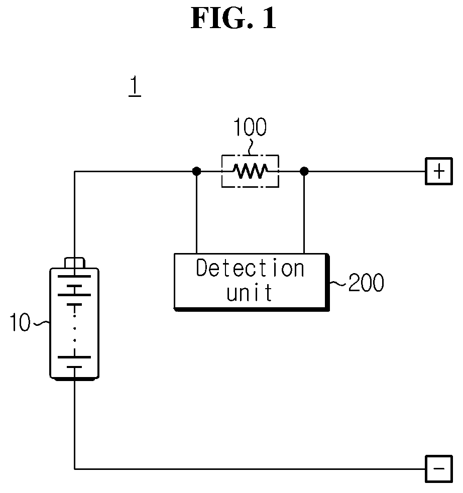
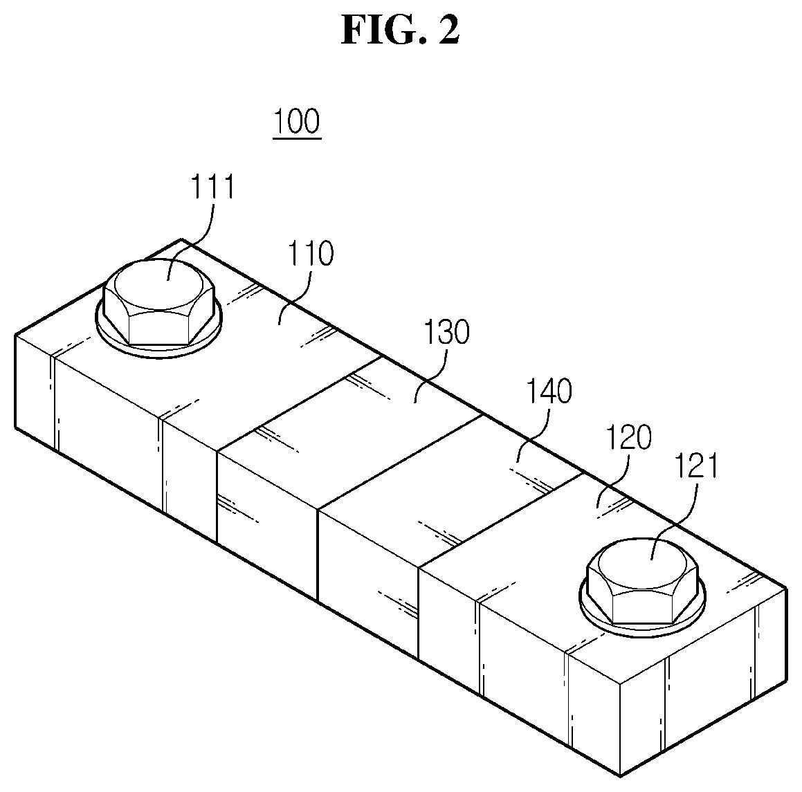
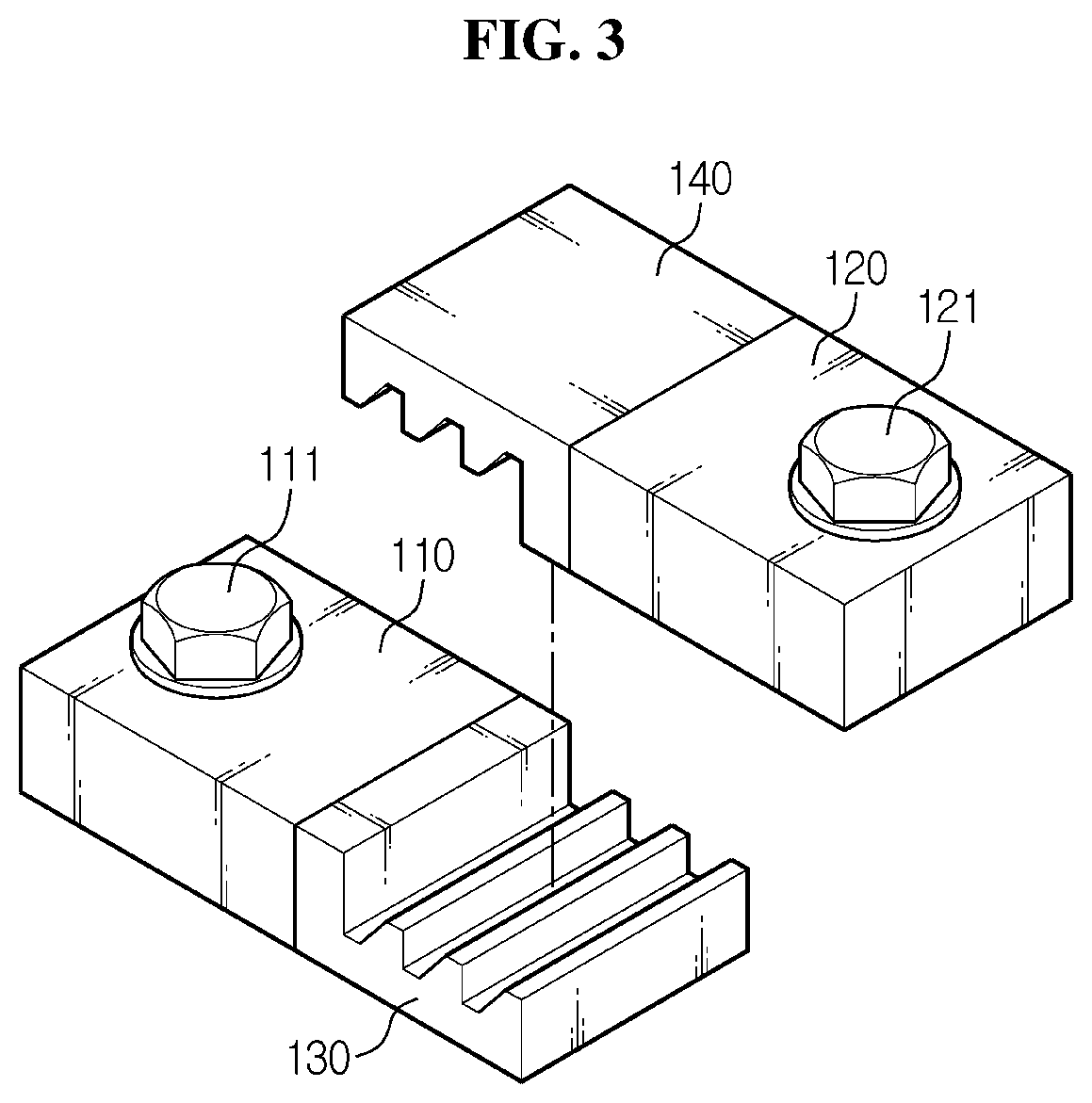
This patent describes a way to adjust the resistance value of a shunt resistor, which can help detect the current flow through it. By adding or removing resistor bars, the resistance value can be very precisely adjusted. This allows for accurate detection of current levels.

Problems solved by technology

To increase the capacity of battery packs, there may be a method that increases the capacity of secondary batteries or battery cells themselves, but in this case, the capacity increase effect is not so large, and there is a physical limitation on the size expansion of the secondary batteries, and another disadvantage is inconvenient management.
When secondary batteries are used in the form of an assembly, for example, the unit secondary batteries may be swollen and damaged by overheat in the event that maloperation occurs due to a flow of overcurrent.
However, when shunt resistors and measurement devices are used to obtain measured values with high reliability, the number of busbars increases, and the battery pack increases in volume and price.
The volume increase of the battery pack has an adverse influence on high efficiency and high energy density.

Method used


Image

  • Shunt Resistor and Apparatus for Detecting Current Including the Same
  • Shunt Resistor and Apparatus for Detecting Current Including the Same
  • Shunt Resistor and Apparatus for Detecting Current Including the Same

Examples


Embodiment Construction

[0035]Hereinafter, the preferred embodiments of the present disclosure will be described in detail with reference to the accompanying drawings. Prior to the description, it should be understood that the terms or words used in the specification and the appended claims should not be construed as being limited to general and dictionary meanings, but interpreted based on the meanings and concepts corresponding to the technical aspects of the present disclosure on the basis of the principle that the inventor is allowed to define the terms appropriately for the best explanation.

[0036]Therefore, the embodiments described herein and illustrations shown in the drawings are just a most preferred embodiment of the present disclosure, but not intended to fully describe the technical aspects of the present disclosure, so it should be understood that a variety of other equivalents and modifications could be made thereto at the time of filing the application.

[0037]Additionally, in describing the p...


PUM


Abstract

A shunt resistor for enhancing accuracy of current detection in the process of detecting current flowing through the shunt resistor and an apparatus for detecting current including the same. The shunt resistor includes two busbars made of an electrically conductive material and spaced apart a predetermined distance, a first connection element made of an electrically conductive material and configured to be mounted in a first busbar provided on one side among the two busbars, and a second connection element made of an electrically conductive material and configured to be mounted in a second busbar provided on the other side among the two busbars. The first connection element and the second connection element are configured to have an increase or decrease in an area of direct or indirect contact between the first connection element and the second connection element.

Description

CROSS-REFERENCE TO RELATED APPLICATIONS[0001]The present application is a national phase entry under 35 U.S.C. § 371 of International Application No. PCT / KR2019 / 003452 filed Mar. 25, 2019, published in Korean, which claims priority from Korean Patent Application No. 10-2018-0035972 filed Mar. 28, 2018, all of which are incorporated herein by reference.TECHNICAL FIELD[0002]The present disclosure relates to a shunt resistor and an apparatus for detecting current including the same, and more particularly, to an improved shunt resistor for enhancing accuracy of current detection in the process of detecting current flowing through the shunt resistor and an apparatus for detecting current including the same.BACKGROUND ART[0003]Recently, there is dramatically growing demand for portable electronic products such as laptop computers, video cameras and mobile phones, and with the extensive development of accumulators for energy storage, robots and satellites, many studies are being made on hi...

Claims


Application Information

Patent Timeline
IPC IPC(8): G01R31/364H01M2/34H01M2/24G01R1/20H01M10/48H01M50/50H01M50/529H01M50/583
CPCH01M2/24H01M2/34G01R31/364G01R1/20H01M10/48H01C1/14G01R31/36G01R31/382G01R1/203G01R15/146H01M50/50H01M50/583Y02E60/10H01M50/502H01M50/529
Inventor MIN, KYOUNG-CHOON
Owner LG ENERGY SOLUTION LTD
Learn More