
Battery charging through multi-stage voltage conversion

a voltage conversion and battery technology, applied in the field of electrochemical energy storage systems, can solve the problems of limiting the use of rechargeable batteries, low efficiency of conventional power converters for such conversion, discharging heat, etc., and achieves the effects of facilitating pumping of high current, preserving battery power, and fast battery charging

Active Publication Date: 2020-06-11
GBATTERIES ENERGY CANADA INC
View PDF5 Cites 4 Cited by
  • Summary
  • Abstract
  • Description
  • Claims
  • Application Information

AI Technical Summary

Benefits of technology

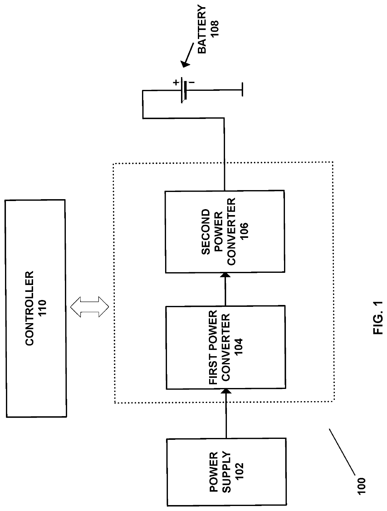
This patent introduces a new technique for charging batteries using multi-stage voltage conversion. This technique helps to fast charge batteries with minimal heat dissipation. It involves generating a charging pulse with multiple stages of voltage conversion, where each stage down-converts the input voltage to create a portion of the charging pulse. This process increases the average current to the battery, while preserving the power provided to it. Overall, this technique helps to efficiently transfer high current into the battery, making it a faster and more effective charge.

Problems solved by technology

However, the problem that limits use of rechargeable batteries is speed of charging the batteries.
The conventionally employed power converters for such conversion have low efficiency, and dissipate heat higher than the designated limit.
Therefore, when the USB-C output is to be converted by the conventional power converter to 4.2V 18A, about 3 watt (W) of heat may be dissipated, which is undesirable.

Method used


Image

  • Battery charging through multi-stage voltage conversion
  • Battery charging through multi-stage voltage conversion
  • Battery charging through multi-stage voltage conversion

Examples


Embodiment Construction

[0019]In the following description, for purposes of explanation, numerous examples and specific details are set forth in order to provide a thorough understanding of the present disclosure. It will be evident, however, to one skilled in the art that the present disclosure as expressed in the claims may include some or all of the features in these examples, alone or in combination with other features described below, and may further include modifications and equivalents of the features and concepts described herein.

[0020]The word “exemplary” is used herein to mean “serving as an example, instance, or illustration.” Any embodiment described herein as “exemplary” is not necessarily to be construed as preferred or advantageous over other embodiments. Likewise, the term “embodiments” does not require that all embodiments include the discussed feature, advantage or mode of operation.

[0021]The terminology used herein is provided to describe particular embodiments only and is not intended t...


PUM

PropertyMeasurementUnit
currentaaaaaaaaaa
currentsaaaaaaaaaa
voltageaaaaaaaaaa

Abstract

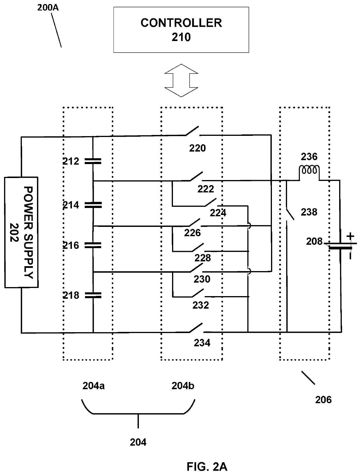
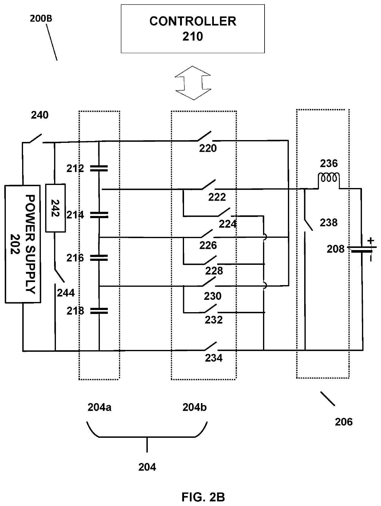
A pulse charging for a battery includes multi-stage voltage conversion. At first stage, an input voltage from a power supply is divided into a plurality of intermediate voltages. At second stage, one or more of the plurality of intermediate voltage are further down converted to generate one or more portions of a charging pulse to be applied to the battery. The down conversion of the input voltage to the output voltage is accompanied by increase in charging current that is applied to the battery. The higher charging current applied to the battery results in fast charging of the battery. Also, the described multi-stage voltage conversion circuitry has high efficiency which alleviates problem of heat dissipation associated with the voltage conversion for charging of the battery.

Description

CROSS REFERENCE TO RELATED APPLICATION[0001]This application is a national phase application from PCT / CA2018 / 050683 filed Jun. 7, 2018, which claims priority to U.S. Provisional Patent Application No. 62 / 518,120, filed on Jun. 12, 2017, the content of all of which is incorporated herein by reference in its entirety for all purposes.BACKGROUND[0002]Rechargeable batteries are electrochemical energy storage systems that are used in numerous applications around the world. However, the problem that limits use of rechargeable batteries is speed of charging the batteries. The speed of charging the batteries is directly proportional to amplitude of current pumped into the batteries. As such, to increase the speed of charging, higher current needs to be provided to the battery.[0003]However, conventionally used energy sources used to charge the batteries for mobile devices are capable of providing current with limited amplitude. Hence, there is a need to employ a power converter to perform v...

Claims


Application Information

Patent Timeline
Patent Type & Authority Applications(United States)
IPC IPC(8): H02J7/00
CPCH02J7/0071H02J7/0019H02J7/00711H02J7/06H02J2207/20H02J7/04H02M3/07H02M3/155H02M1/007
Inventor TKACHENKO, OLEKSANDRSHERSTYUK, MYKOLAPRODIC, ALEKSANDARMCRAE, TIMOTHYRADOVIC, IVANPUZAKOV, OLEKSANDR
Owner GBATTERIES ENERGY CANADA INC
Learn More