Battery charger

a battery charger and battery technology, applied in the direction of energy-saving power electronics conversion, sustainable buildings, and electric variable regulation, can solve the problems of reducing the lifespan of the battery, increasing heating, and adversely affecting the electrolyte conductivity and electrochemical reactions at the electrode-electrolyte interface, so as to reduce the cost and size of the battery charger, and increase the capacitance

Inactive Publication Date: 2018-08-02
DYSON TECH LTD
View PDF5 Cites 9 Cited by
  • Summary
  • Abstract
  • Description
  • Claims
  • Application Information

AI Technical Summary

Benefits of technology

[0006]In order to generate a regular output current whilst simultaneously drawing a sinusoidal input current, the PFC circuit of a conventional battery charger typically requires a capacitor of high capacitance. With the battery charger of the present invention, on the other hand, the PFC circuit may employ a capacitor of much smaller capacitance, or indeed no capacitor at all, thereby further reducing the cost and size of the battery charger. Where a capacitor is employed, the capacitor will be held at a voltage that is proportional to the voltage of the battery. In the absence of any voltage converter, the capacitor is held at the battery voltage. If, on the other hand, the battery charger comprises a voltage converter, the capacitor of the PFC circuit is held at the battery voltage multiplied by the voltage conversion ratio of the converter.
[0007]The PFC circuit may adjust the average value of the input current in response to changes in the voltage of the battery. By adjusting the average value of the input current in response to changes in the battery voltage, the battery charger is better able to control the charge rate. The PFC circuit may increase the average value of the input current in response to an increase in the voltage of the battery. Consequently, a similar charge rate may be achieved during charging. The PFC circuit may adjust the average value of the input current in response to changes in the voltage of the battery such that average value of the output current is constant. This then has the advantage that a constant charge rate may be achieved.
[0008]The battery charger may operate in a first mode when the voltage of the battery is less than a threshold, and the battery charger may switch to a second mode when the voltage of the battery exceeds the threshold. The PFC circuit may then cause the input current to be drawn from the AC source during each and every half-cycle of the input voltage supplied by the AC source when operating in the first mode, but cause the input current to be drawn from the AC source during only some of the half-cycles of the input voltage when operating in the second mode. As a result, the battery charger generates a continuous output current when operating in the first mode and a discontinuous output current when operating in the second mode. When operating in the first mode, relatively quick charging of the battery may be achieved by virtue of the continuous output current. When operating in the second mode, rest periods are introduced during which no output current is generated. These rest periods allow the chemical actions within the battery and thus the voltage of the battery to stabilize before recommencing charging. The first mode may therefore be used to charge the battery rapidly to the voltage threshold, and the second mode may be used to top-up the battery as the battery undergoes voltage relaxation.
[0009]The battery charger may comprise a step-down DC-to-DC converter located between the PFC circuit and the output terminals. The voltage conversion ratio of the DC-to-DC converter may then be defined such that the peak value of the input voltage of the AC source, when stepped down, is less than the minimum voltage of the battery. This then has the advantage that the PFC circuit is able to operate in boost mode to provide continuous current control.
[0010]The DC-to-DC converter may comprise a resonant converter having one or more primary-side switches that are switched at a constant frequency. Employing a resonant converter has the advantage that the desired voltage conversion ratio may be achieved through the turns ratio of the transformer. Additionally, a resonant converter is able to operate at higher switching frequencies than a comparable PWM converter and is capable of zero-voltage switching. By switching the primary-side switches at a constant frequency, a relatively simple controller may be employed by the DC-to-DC converter. Switching at a constant frequency is made possible because the DC-to-DC converter is not required to regulate or otherwise control the output voltage. In contrast, the DC-to-DC converter of a conventional power supply is generally required to regulate the output voltage and thus requires a more complex and expensive controller in order to vary the switching frequency.
[0011]The DC-to-DC converter may have one or more secondary-side switches that are switched at the same constant frequency as that of the primary-side switches. A relatively simple and cheap controller may therefore be employed on the secondary side. Moreover, a single controller could conceivably be employed to control both the primary-side and the secondary-side switches.

Problems solved by technology

Conventional wisdom dictates that charging a battery with currents having relatively large ripple reduce the lifespan of the battery.
In particular, time-varying currents lead to increased heating, which adversely affects the electrolyte conductivity as well as the electrochemical reactions at the electrode-electrolyte interfaces.

Method used


Image

  • Battery charger
  • Battery charger
  • Battery charger

Examples


Embodiment Construction

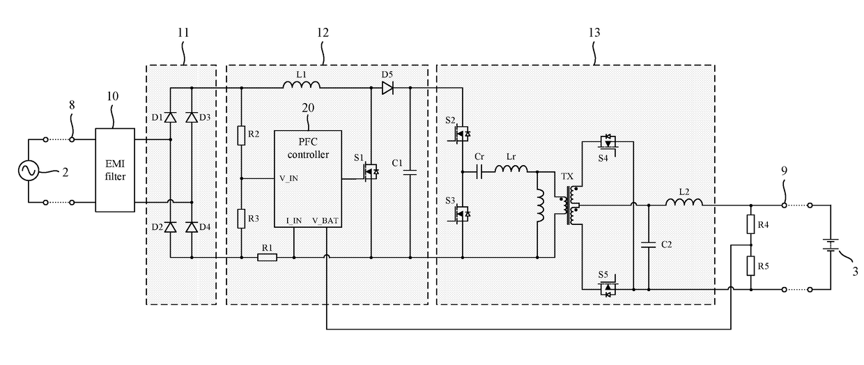
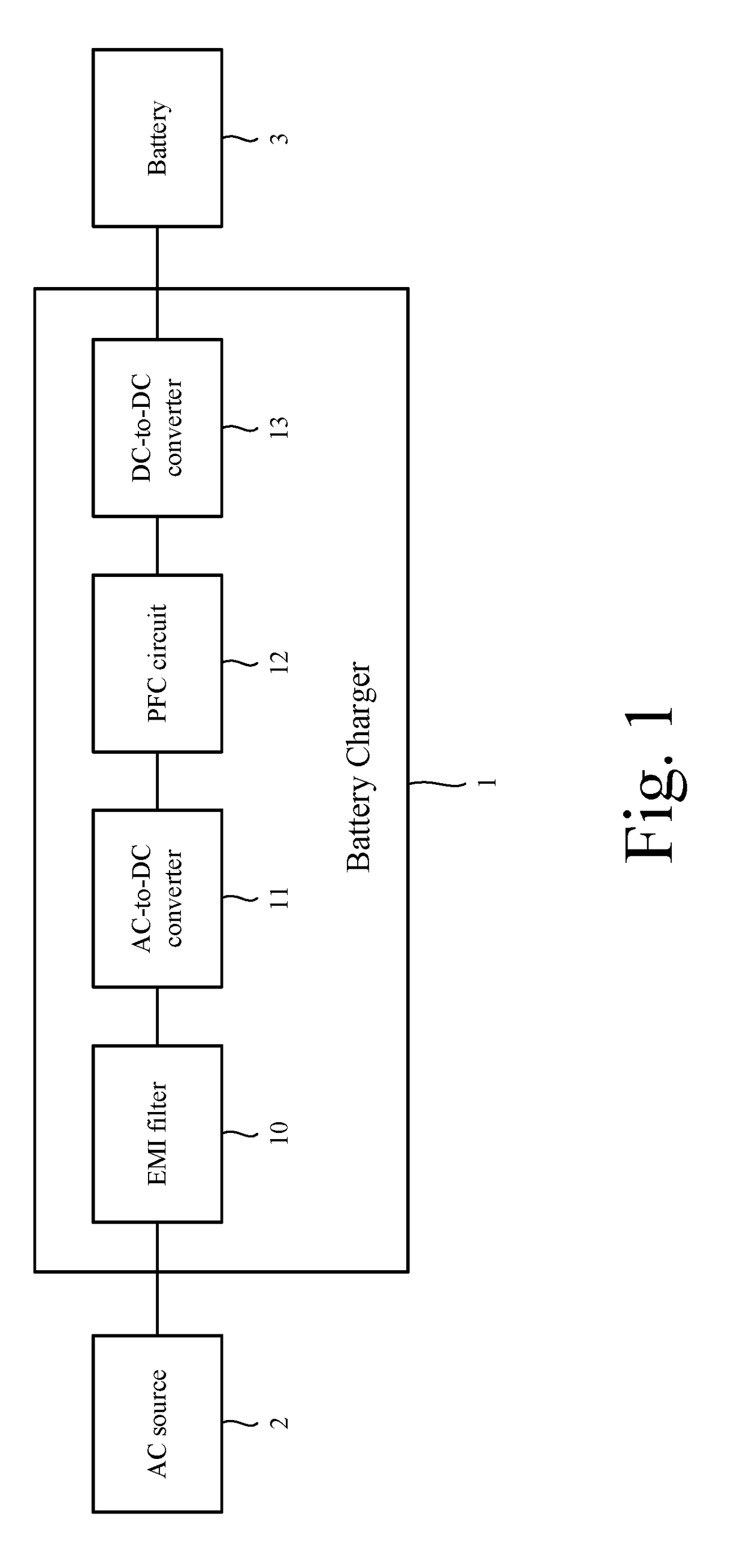
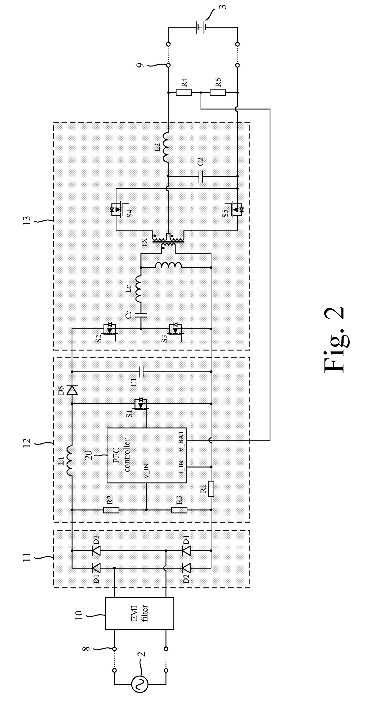
[0030]The battery charger 1 of FIGS. 1 and 2 comprises input terminals 8 for connection to an AC source 2, and output terminals 9 for connection to a battery 3 to be charged. The battery charger 1 further comprises an electromagnetic interference (EMI) filter 10, an AC-to-DC converter 11, a power factor correction (PFC) circuit 12, and a DC-to-DC converter 13 connected between the input terminals 8 and the output terminals 9.

[0031]The EMI filter 10 is used to attenuate high-frequency harmonics in the input current drawn from the AC source 2.

[0032]The AC-to-DC converter 11 comprises a bridge rectifier D1-D4 providing full-wave rectification.

[0033]The PFC circuit 12 comprises a boost converter located between the AC-to-DC converter 11 and the DC-to-DC converter 13. The boost converter comprises an inductor L1, a capacitor C1, a diode D5, a switch S1 and a control circuit. The inductor, capacitor, diode and switch are arranged in a conventional arrangement. Consequently, the inductor L...


PUM


Abstract

A battery charger comprising input terminals for connection to an AC source, output terminals for connection to a battery to be charged, and a power factor correction (PFC) circuit connected between the input terminals and the output terminals. The PFC circuit comprises a current control loop for regulating an input current drawn from the AC source. The voltage at the output of the PFC circuit is regulated by the voltage of the battery which is reflected back to the PFC circuit. As a result, the battery charger acts as a current source that outputs an output current at the output terminals, and the waveform of the output current is periodic with a frequency twice that of the input current and a ripple of at least 50%.

Description

REFERENCE TO RELATED APPLICATIONS[0001]This application is a national stage application under 35 USC 371 of International Application No. PCT / GB2016 / 051976, filed Jun. 30, 2016, which claims the priority of United Kingdom Application No. 1512854.9, filed Jul. 21, 2015, the entire contents of each of which are incorporated herein by reference.FIELD OF THE INVENTION[0002]The present invention relates to a battery charger.BACKGROUND OF THE INVENTION[0003]A battery charger may comprise a power factor correction (PFC) circuit that generates a regular output current for use in charging the battery whilst simultaneously drawing a sinusoidal input current from an AC source. In order to achieve this, the PFC circuit typically comprises a current control loop for regulating the input current, and a voltage control loop for regulating the output voltage.SUMMARY OF THE INVENTION[0004]The present invention provides a battery charger comprising input terminals for connection to an AC source, outp...

Claims


Application Information

Patent Timeline
Patent Type & Authority Applications(United States)
IPC IPC(8): H02M1/42H02J7/02H02J7/04H02M3/335H02M1/08H02M1/12
CPCH02J7/045H02M2001/0058H02M1/083H02J7/022H02M3/33576H02M1/4241H02M1/12H02M1/4208H02M1/4225H02M1/4258H02J2207/20H02J7/02Y02B40/00Y02B70/10Y02P80/10H02M1/0058
Inventor GREETHAM, STEPHENBERRY, STEPHENKOTTE, HARI BABURADHIKA, AMBATIPUDI
Owner DYSON TECH LTD
Why Eureka
Try Eureka