
Hydraulic valve system with a valve housing and method for manufacturing a valve housing

a valve system and valve housing technology, applied in valve housings, manufacturing tools, transportation and packaging, etc., can solve the problems of unsuitable in particular for portable mobile hydraulic applications, the valve housing is regularly relatively heavy, and the valve housing is regularly relatively complex, so as to achieve the effect of cheaper manufacturing

Active Publication Date: 2020-06-18
HAWE HYDRAULIK SE
View PDF0 Cites 2 Cited by
  • Summary
  • Abstract
  • Description
  • Claims
  • Application Information

AI Technical Summary

Benefits of technology

The invention provides a connection block that allows for easy and quick replacement of different hole patterns for hydraulic valve systems. This results in a compact and lightweight valve housing that can be used in portable mobile hydraulic systems. The connection block has pre-defined hole patterns, which can be standardized or customized. The round steel can be easily cut to the required length and can be provided as bar material, allowing for fast and simple turning using a lathe. Overall, the invention results in a more flexible, standardized, and portable hydraulic valve system.

Problems solved by technology

A disadvantage of the well-known hydraulic valve systems is that they regularly have a relatively complex valve housing in order to be able to accommodate all channels or lines within the housing.
This in turn means that the valve housings are regularly relatively heavy and are therefore unsuitable in particular for portable mobile hydraulic applications.

Method used


Image

  • Hydraulic valve system with a valve housing and method for manufacturing a valve housing
  • Hydraulic valve system with a valve housing and method for manufacturing a valve housing
  • Hydraulic valve system with a valve housing and method for manufacturing a valve housing

Examples


Embodiment Construction

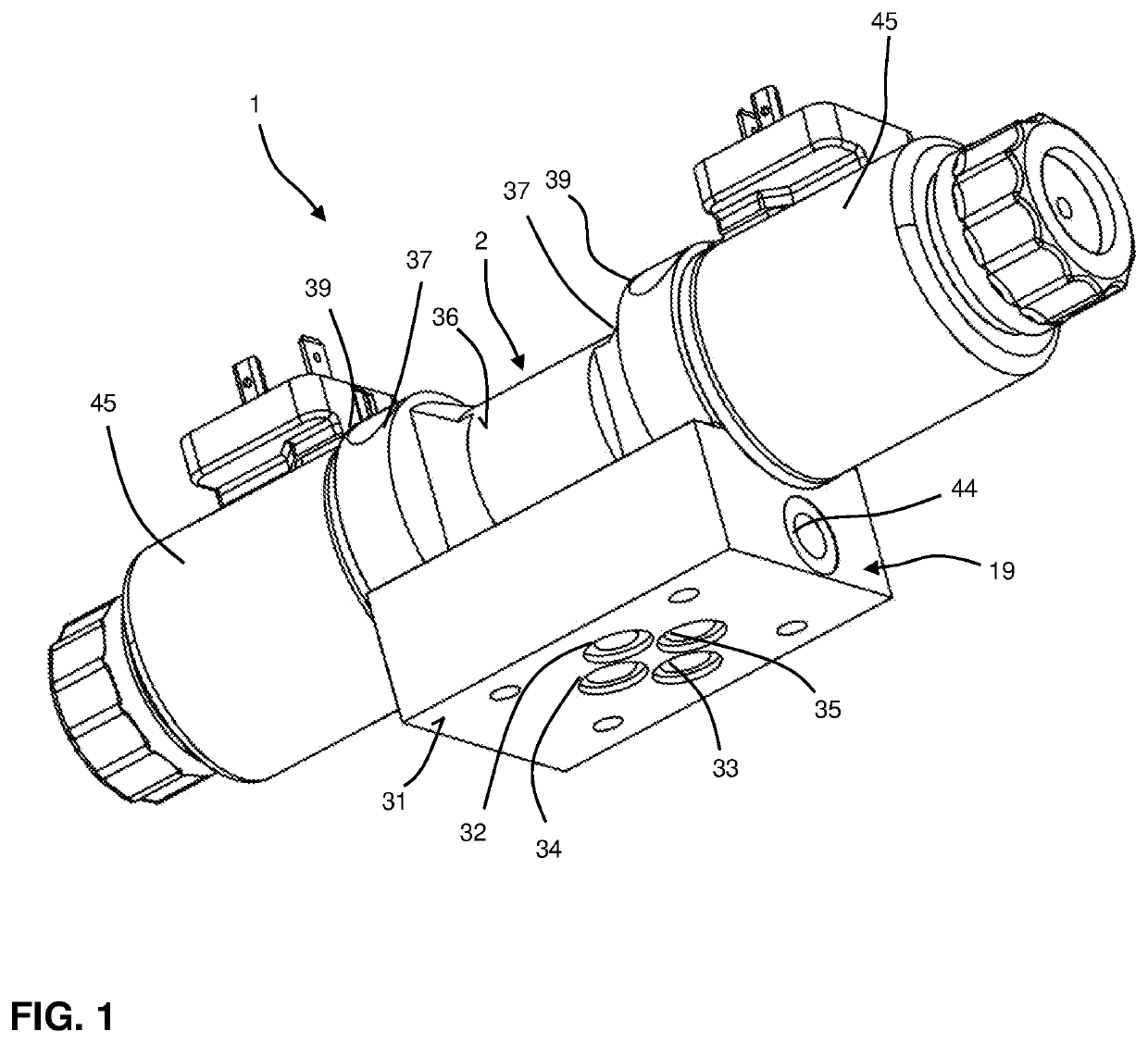
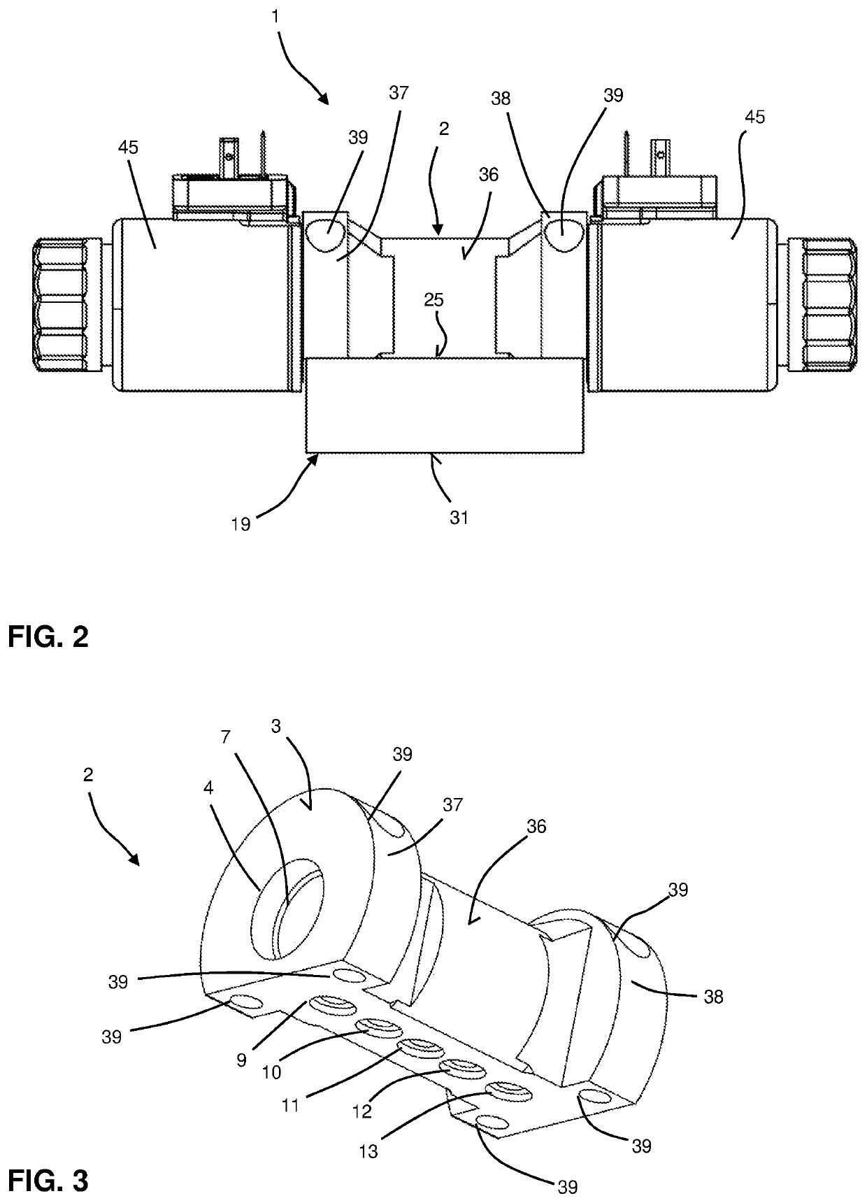
[0049]FIGS. 1 and 2 show a hydraulic valve system 1 according to a first embodiment of the invention. The hydraulic valve system 1 has a one-piece valve housing 2, a connection block 19 fixed fluid-tightly to the valve housing 2 and two actuators 45. The actuators 45 are configured to move one or more pistons (not shown) arranged in valve housing 2 between different switching positions. In this embodiment, the actuators 45 are conventional electromagnetic actuators, so that the actuators 45 will not be discussed in detail in the following.

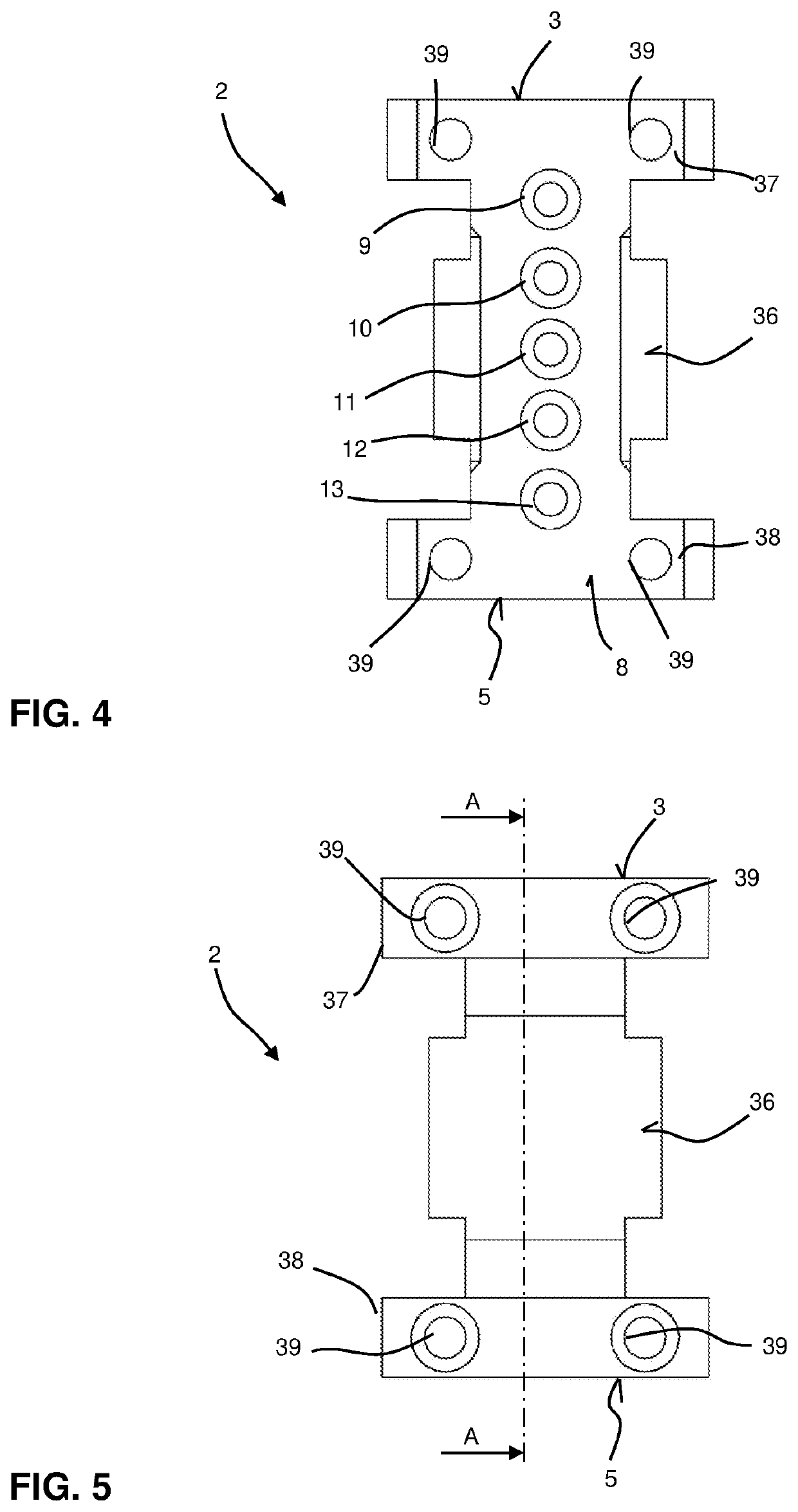
[0050]In the following, valve housing 2 according to the first embodiment is described with reference to FIGS. 3 to 9. The valve housing 2 has a first axial flange 37 with a first connection side 3 and a first piston opening 4 and a second axial flange 38 with a second connection side 5 and a second piston opening 6. From the first piston opening 4 to the second piston opening 6, a stepless through-hole 7 extends to accommodate the piston or piston...


PUM

PropertyMeasurementUnit
cylindrical shapeaaaaaaaaaa
lengthaaaaaaaaaa
axial lengthaaaaaaaaaa

Abstract

A hydraulic valve system has a valve housing, which has a first connection side and a second connection side. The valve housing has a through-hole for accommodating at least one piston. The valve housing has a third connection side with at least three hydraulic connections which are each connected to the through-hole via a line. The hydraulic valve system has a connection block with at least three hydraulic through-lines each extending from a first connection opening arranged on a housing side of the connection block to at least one second connection opening arranged on a hole pattern side opposite the housing side. Each of the at least three first connection openings is connected in a fluid-tight manner to one of the at least three hydraulic connections, and the second connection openings are arranged in a pre-defined hole pattern. A method for manufacturing a valve housing is also disclosed.

Description

CROSS-REFERENCE TO RELATED APPLICATION[0001]This application claims priority from German Application No. DE 10 2018 221 689.4 filed Dec. 13, 2018, the entire content of which is incorporated herein by reference.FIELD OF THE INVENTION[0002]The present invention relates to a hydraulic valve system with a valve housing and a method for manufacturing a valve housing.BACKGROUND OF THE INVENTION[0003]Such valve housings regularly have a first connection side and a second connection side opposite the first connection side. The first connection side has a first piston opening and the second connection side has a second piston opening. A through-hole for receiving at least one piston extends from the first piston opening to the second piston opening. Furthermore, such valve housings normally have a third connection side with at least three hydraulic connections, each of which is connected to the through-hole via a line.[0004]A disadvantage of the well-known hydraulic valve systems is that th...

Claims


Application Information

Patent Timeline
Patent Type & Authority Applications(United States)
IPC IPC(8): F16K27/02B21D53/10
CPCF16K27/0263B21D53/10F15B2211/30525F15B13/02B23P15/001F16K27/04F15B13/08B23B5/06Y10T137/87885
Inventor ANEDER, GEORG
Owner HAWE HYDRAULIK SE
Learn More