Triggered vacuum gap fault detection methods and devices

a vacuum gap and fault detection technology, applied in the direction of measurement devices, conductor types, fault locations, etc., can solve the problems of increasing the load on the network, affecting the current flow from the substation, and affecting the fault detection effect of the substation

Pending Publication Date: 2020-06-18
S&C ELECTRIC
View PDF1 Cites 6 Cited by
  • Summary
  • Abstract
  • Description
  • Claims
  • Application Information

AI Technical Summary

Benefits of technology

[0009]In another embodiment, an apparatus for the fault detection device is provided. The fault detection device includes an interface, a voltage sensing arrangement coupled to the interface to measure a voltage at the interface, a current sensing arrangement coupled to the interface to obtain a measurement of a temporary current flow at the interface, a vacuum gap switching arrangement coupled to the interface, and a control

Problems solved by technology

Periodically, faults occur in the distribution network as a result of various things, such as animals touching the lines, lightning strikes, tree branches falling on the lines, vehicle collisions with utility poles, etc.
Faults may create a short-circuit that increases the load on the network, which may cause the current flow from the substation to significantly increase, for example, many times above the normal current, along the fault path.
This amount of current causes the electrical lines to significantly heat up and possibly melt, and also could cause mechanical damage to various components in the substation and in the network.
Thus, these types of low impedance faults in transmission and distribution systems that may result in outages or equipment damage are a significant concern for electric power utilities because of high fault currents flowing during such faults.
Thus, if a fault persists, reclosing contributes to system reliability issues by re-exposing the system to the fau

Method used


Image

  • Triggered vacuum gap fault detection methods and devices
  • Triggered vacuum gap fault detection methods and devices
  • Triggered vacuum gap fault detection methods and devices

Examples


Embodiment Construction

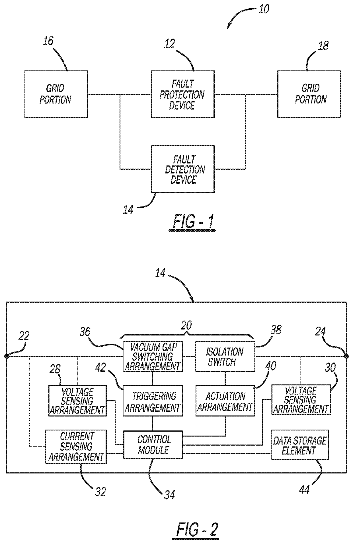
[0022]The following discussion of the embodiments of the disclosure directed to a fault detection device including a vacuum gap switching element is merely exemplary in nature and is in no way intended to limit the disclosure or its applications or uses.

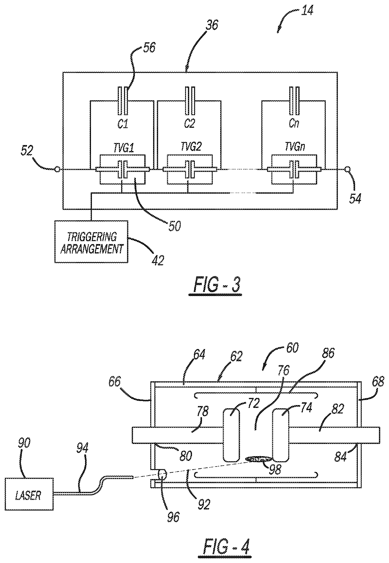
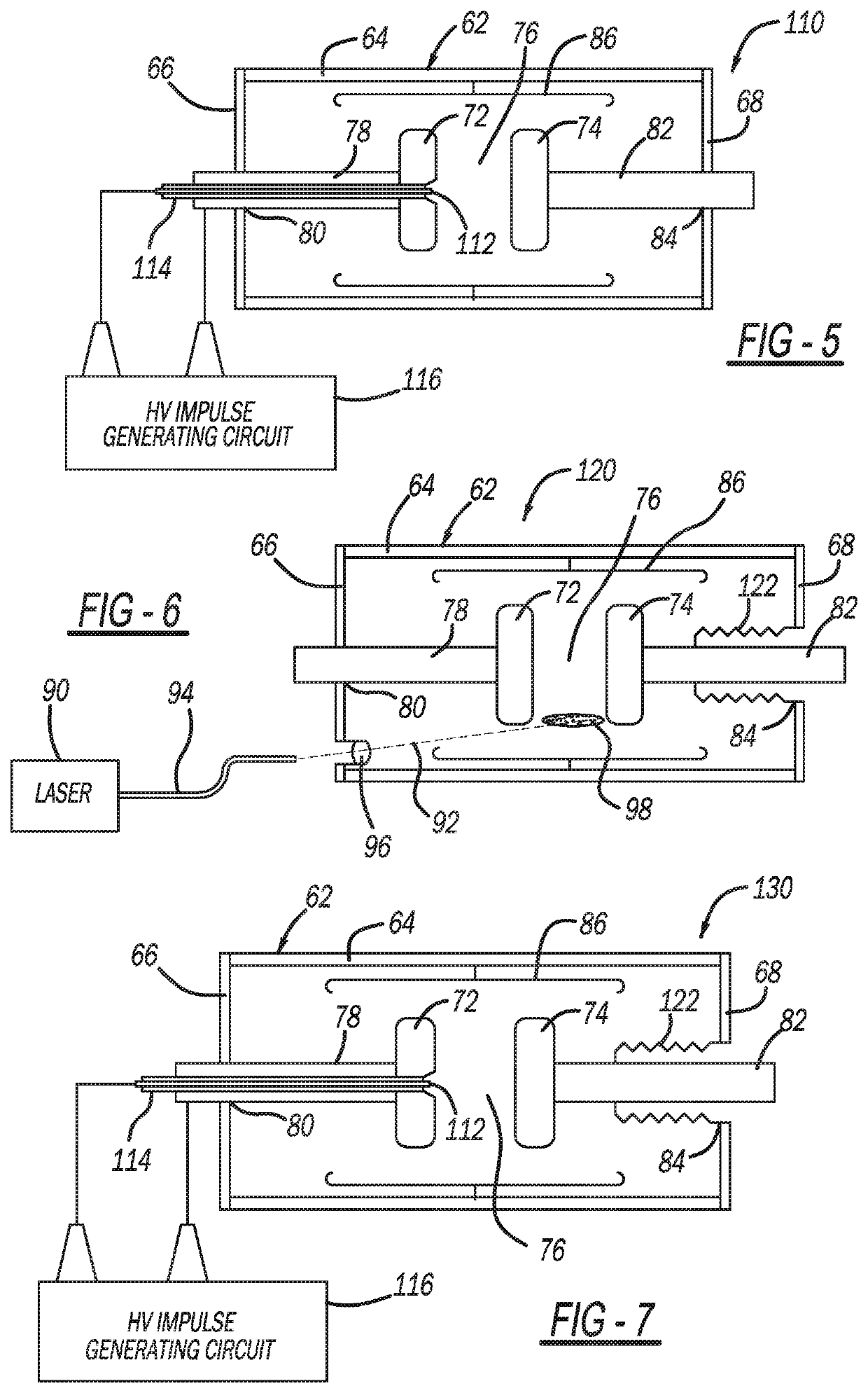
[0023]Embodiments of the subject matter described herein relate to operating fault detection devices in an electrical energy transmission system to mitigate the impact of fault conditions when closing (or reclosing) a fault protection device. As described in greater detail below, in exemplary embodiments, a fault detection device is configured electrically parallel to a primary fault protection device to test for the presence of a fault condition prior to closing a switching element of the fault protection device. The fault detection device utilizes one or more triggered vacuum gap switching elements that are triggered or otherwise activated to allow a temporary current flow through the fault detection device, which may be analyzed, ...


PUM


Abstract

A system and method for determining if a fault condition exists in an electrical network. The method includes determining that a fault protection device has been opened and monitoring a voltage angle of a voltage waveform across a vacuum gap switching arrangement if the fault protection device is open, where the vacuum gap switching arrangement includes at least one vacuum gap switching element. The method also includes triggering a breakdown of a vacuum gap in the at least one vacuum gap switching element when the voltage angle corresponds to a predetermined switching angle to enable a temporary current flow through the vacuum gap switching arrangement, measuring the current flow through the vacuum gap switching arrangement, and determining whether the fault condition exists based at least in part on the measured current flow.

Description

CROSS-REFERENCE TO RELATED APPLICATION[0001]This application claims the benefit of the filing date of U.S. Provisional Application No. 62 / 718,139, filed Dec. 18, 2018, and titled Triggered Vacuum Gap Fault Detection Methods And Devices.BACKGROUNDField[0002]This disclosure relates generally to a fault detection device including a vacuum gap switching element and, more particularly, to a fault detection device including a plurality of vacuum gap switching elements, where the fault detection device causes breakdown of the vacuum gap switching elements in response to a certain measured voltage angle to provide pulse testing for detecting fault current.Discussion of the Related Art[0003]An electrical power distribution network, often referred to as an electrical grid, typically includes a number of power generation plants each having a number of power generators, such as gas turbines, nuclear reactors, coal-fired generators, hydro-electric dams, etc. The power plants provide power at a v...

Claims


Application Information

Patent Timeline
IPC IPC(8): G01R31/08G01R31/327
CPCG01R31/086G01R31/3274G01R31/1254
Inventor DJOGO, GORANENNIS, MICHAEL
Owner S&C ELECTRIC
Why Eureka
Try Eureka