Dual Energy Solar Thermal Power Plant

Inactive Publication Date: 2013-04-04
KUO CHANG
View PDF23 Cites 6 Cited by
  • Summary
  • Abstract
  • Description
  • Claims
  • Application Information

AI Technical Summary

Benefits of technology

[0015]A solar energy collector comprises a solid body having a substantially flat, planar solar energy absorbing collecting surface. The solid body has a first thickness at a center portion tapering to a second thickness at each of a pair of opposing edge portions defining a width of the body. A bore extends completely through the body along its length and is aligned along an axis at the center portion. A thin window transparent at selected solar energy wavelengths (for example, ultra violet solar radiation)

Problems solved by technology

However, the results have been less than expected.
Generally, the bankers are hesitant to commit capital to solar power plant projects because the capital returns are less than anticipated.
This is a disadvantage for human ambition to harness the solar power.
The vast amount of solar energy has not been continuously utilized day after day.
Yet this is far below the 35% efficiency of a nuclear power plant, or 38% for a fossil power plant.
Another shortcoming is that the power generated in this system is at low direct current (DC) voltage and is thus not suitable for long-distance transmission to electrical power users.
The equipment cost of a photovoltaic solar power system would be too high for a large output, for example, the 300 mega-watts clas

Method used


Image

  • Dual Energy Solar Thermal Power Plant
  • Dual Energy Solar Thermal Power Plant
  • Dual Energy Solar Thermal Power Plant

Examples


Embodiment Construction

[0078]Persons of ordinary skill in the art will realize that the following description of the present invention is illustrative only and not in any way limiting. Other embodiments of the invention will readily suggest themselves to such skilled persons.

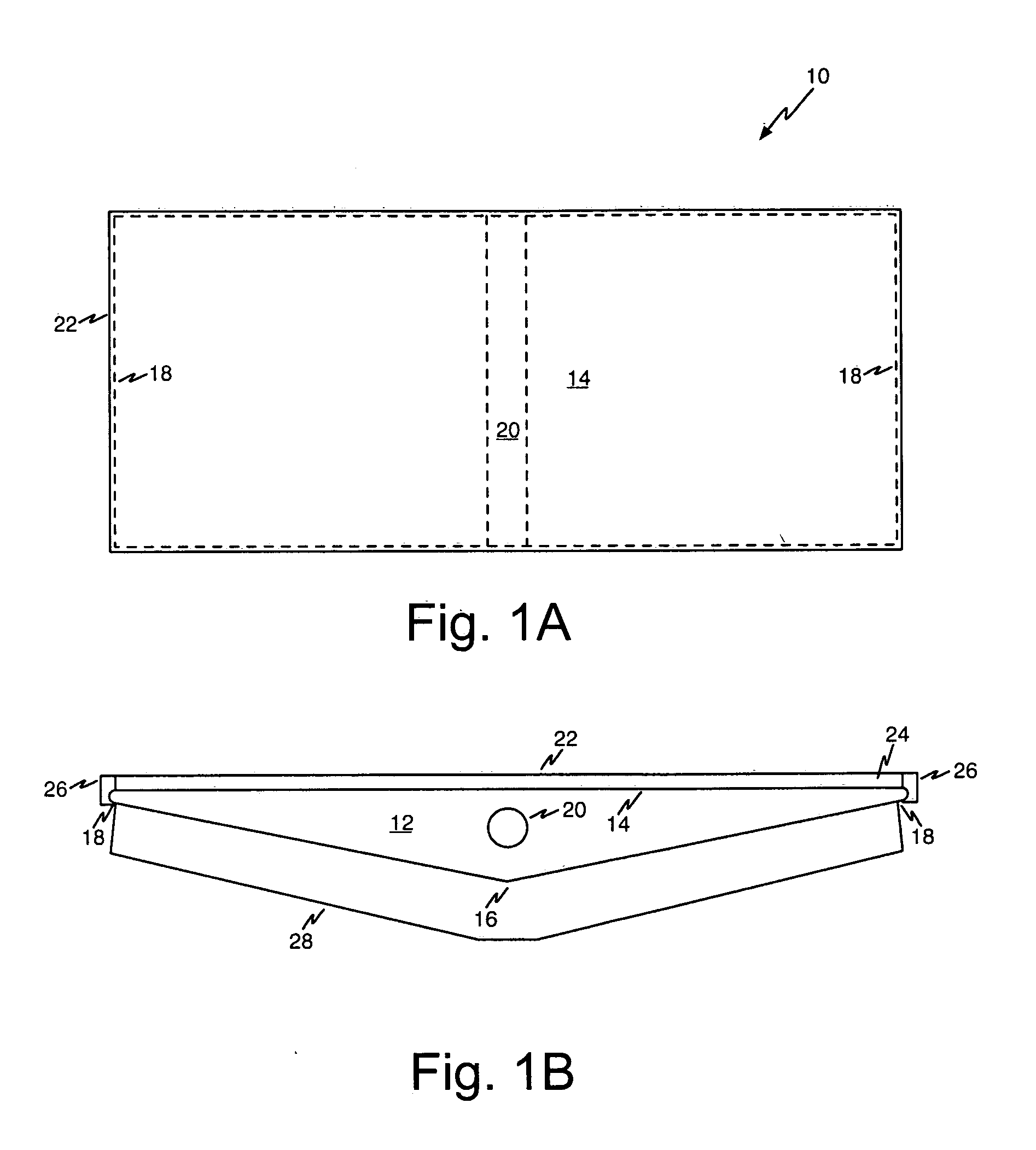
[0079]Referring first to FIGS. 1A and 1B, diagrams show top and cross-sectional views, respectively, of an illustrative solar energy collector 10 in accordance with one aspect of the present invention.

[0080]The solar energy collector 10 comprises a solid body 12 having a substantially flat planar solar energy absorbing collecting surface 14. The body 12 is formed from an efficient heat conductive material, yet the cost is low enough to make the power plant feasible. The planar solar energy absorbing collecting surface 14 should be configured to maximize energy absorption. In some embodiments of the invention, the collecting surface 14 is black in color. The body 12 may be formed from a metal, such as aluminum. The body 12 may be forme...


PUM


Abstract

A solar energy collector comprises a solid body having a substantially planar solar energy absorbing collecting surface. The solid body has a first thickness at a center portion tapering to a second thickness at each of a pair of opposing edge portions defining a width of the body. A bore extends completely through the body along its length and is aligned along an axis at the center portion. A window transparent at most solar radiation in the visible spectrum and near UV to infrared-red solar energy wavelengths is disposed at a distance from the collecting surface, the window sealed around a periphery of the collecting surface to define a sealed vacuum gap between the collecting surface and the bottom surface of the window. The solar energy collector is a major component of a large scale solar thermal power plant.

Description

BACKGROUND[0001]1. Field of the Invention[0002]The present invention relates to the design of dual sources solar and thermal power generation. More particularly, the present invention relates to a design of power plant with solar collectors and associated thermal power generating equipment, utilizing the proposed particular solar energy collectors, auxiliary boiler / steam superheater and all thermal power generation supporting systems.[0003]2. Discussion of Related Art[0004]The amount of solar energy that falls on the surface of earth per minute is equivalent to burning 100,000,000 tons of coal per minute. The average solar energy per square cm on the earth's surface per minute is about 2 calories. This is equivalent to 4,423 BTU per square foot per day. The solar energy received on each individual area will be different depending on the cloud, moisture in atmosphere, dust in the air, location and season. In the southwestern United States from Las Vegas to the Mexican border along th...

Claims


Application Information

Patent Timeline
IPC IPC(8): F03G6/00F24J2/50
CPCF24J2/50F24J2/242F24J2/5233Y02E10/46Y02B10/22Y02E10/44F24J2/525F24S10/72F24S25/13F24S80/50F24S25/617F24S80/58Y02B10/20
Inventor KUO, CHANG
Owner KUO CHANG
Why Eureka
Try Eureka