Solid state cooling or power generating device and method of fabricating the same

a technology of solid-state cooling and power generation, which is applied in the direction of sustainable buildings, light and heating apparatus, machine operation modes, etc., can solve the problems of phonon heat conduction (blockage), no commercial products exist on the market, and vacuum gap devices cannot compete, etc., to achieve reasonable cost, high efficiency, and small

Inactive Publication Date: 2007-12-20
BEAKON TECH
View PDF5 Cites 6 Cited by
  • Summary
  • Abstract
  • Description
  • Claims
  • Application Information

AI Technical Summary

Benefits of technology

[0026] The solid state cooling / power generating device based on vacuum gap according to the invention has very high efficiency and which is possible to manufacture at reasonable costs.
[0027] One advantage of the solid state cooling / power generating device according to the invention is that it can be made small and therefore is well suited for cooling electronic device. It can even be integrated in computer chips. The device comprises no moving parts, which is a prerequisite for the reduction of sizes, and also ensures a robustness and reliability.
[0028] A further advantage as compared to Peltier elements, is the efficiency. The vacuum gap device according to the invention can be up to 10-15 times more efficient than conventional Peltier elements.

Problems solved by technology

Due to these constrains the vacuum gap devices have not been able to compete with the well known Peltier elements, and no commercial products exist on the market today.
A few years later it was found that phonon heat conduction (which was blocked by the vacuum gap) played a very destructive role, basically rendering the efficiency of these devices on par (or worse) with the Peltier element.
However, to the extent of the knowledge of the inventor no working prototype or commercial product exists.
It is, with today known manufacturing methods, exceedingly difficult to produce chips with such large area and a vacuum gap in the order of 10-20 Å.
The arrangement blocks tunneling of low energy electrons (lower than the Fermi energy) which otherwise diminishes the efficiency of a TH without any insulator layer, by altering the shape of the electrical field between the electrodes.
A high cooling power is reported; however, the efficiency of the device is still low, due to the large applied electric field.

Method used


Image

  • Solid state cooling or power generating device and method of fabricating the same
  • Solid state cooling or power generating device and method of fabricating the same
  • Solid state cooling or power generating device and method of fabricating the same

Examples


Embodiment Construction

[0036] Thermotunnelling vacuum gap heatpumps have, as discussed in the background section, the potential of delivering very high efficiency as compared to Peltier elements in for example cooling devices. However, the promising theoretical calculations and simulations have shown to be extremely difficult to realize with existing manufacturing methods. The main problem with the prior art suggested vacuum gap heatpumps is the requirement of a vacuum gap in the order of 1-50 Å and with an area of around 1 cm2 to be able to provide commercially interesting products. Providing such large electrodes with a gap of that order is with today known methods, at least with an acceptable yield, impossible. Surface roughness, impurities, etc. will unavoidable lead to large variations in the width of the gap, and probably contact between the electrodes in some points, seriously impairing the function of the heatpump.

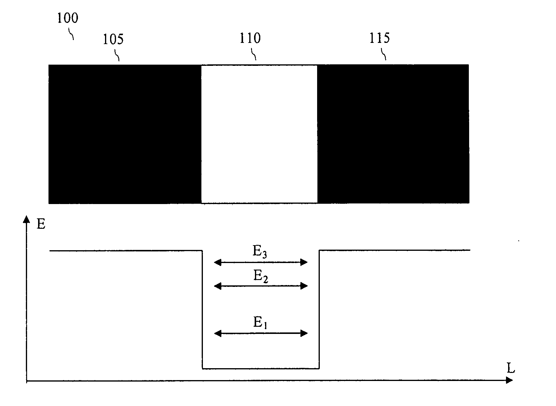
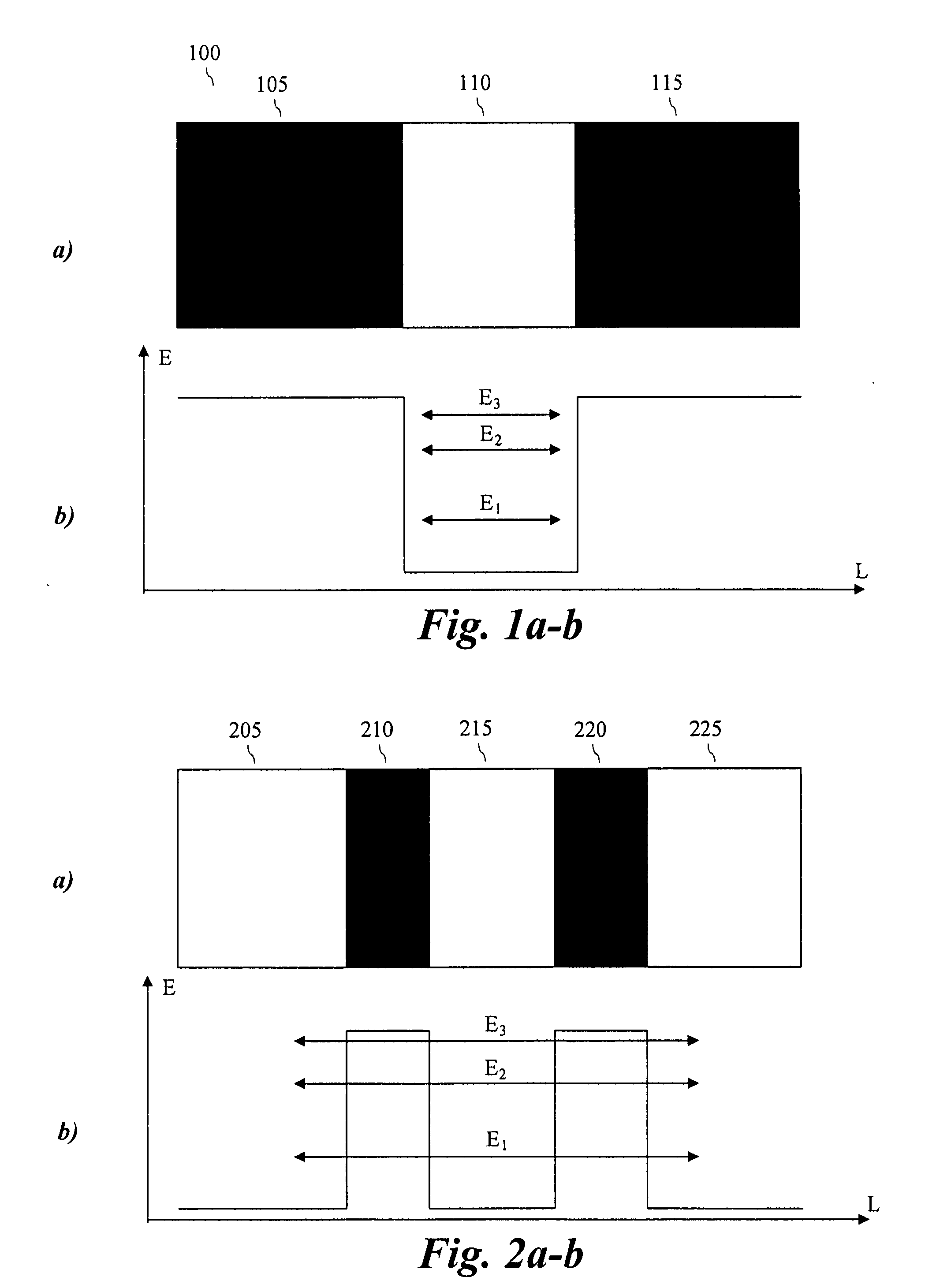
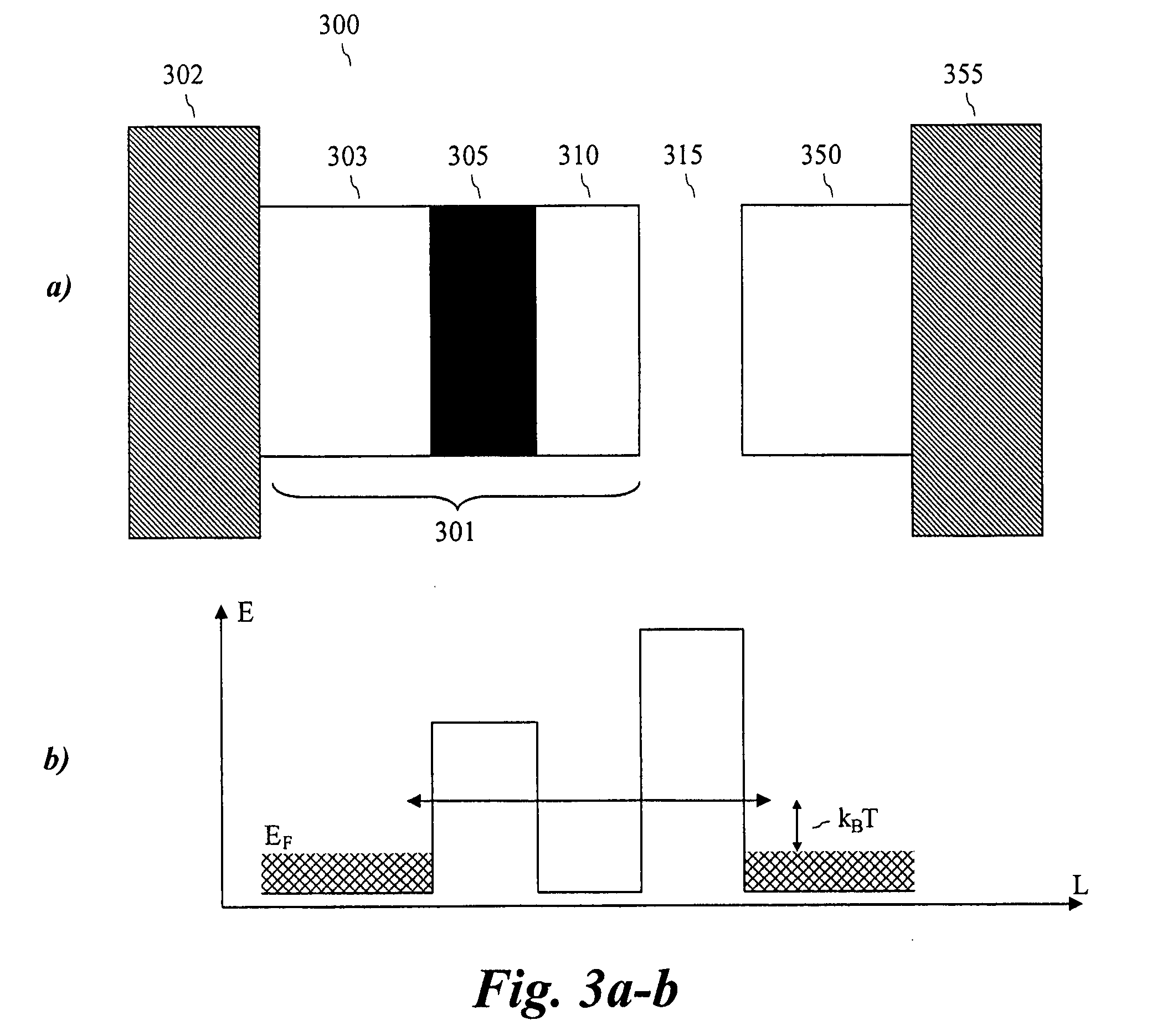
[0037] According to the present invention, a nanoscaled semiconductor heterostructu...


PUM

PropertyMeasurementUnit
work functionsaaaaaaaaaa
sizeaaaaaaaaaa
sizeaaaaaaaaaa

Abstract

The present invention relates to a solid state cooling / power generating device is provided comprising a first and second electrode separated by a vacuum gap. According to the present invention at least one of the electrodes is provided with a nanoscaled heterostructure 301, which comprises at least one quantum well which in combination with the vacuum gap 315 forms a double barrier resonance structure providing conditions which allows resonant tunneling between the first and second electrode.

Description

[0001] The present application claims benefit of U.S. Provisional Patent Application Ser. No. 60 / 796,531, filed May 2, 2006, which is incorporated by reference in its entirety.FIELD OF THE INVENTION [0002] The present invention relates to a solid state cooling and / or power generating device. In particular the invention relates to a heatpump comprising nanoscaled semiconductor heterostructures. BACKGROUND OF THE INVENTION [0003] The interest in solid state cooling devices has over the last decades shown a significant increase. A solid state cooling device is driven directly by electrical current and the simultaneous cooling and heating of different parts of the device is due to thermoelectrical effects. The solid state cooling devices are typically less effective than conventional refrigerators, but have the advantage of not relying on any moving mechanical parts or needing potentially harmful heat transfer fluids. These features, and the fact that a solid state cooling device can be...

Claims


Application Information

Patent Timeline
Patent Type & Authority Applications(United States)
IPC IPC(8): F25B21/02H01S4/00
CPCF25B21/00F25B2321/003Y10T29/49002H01L35/00Y02B30/66H01J45/00Y02B30/00H10N10/00H01J21/02B82Y25/00H10N15/00
Inventor LARSSON, MAGNUS
Owner BEAKON TECH
Why Eureka
Try Eureka