Vacuum glass and processing method thereof

A technology of vacuum glass and processing method, applied in glass forming, glass re-forming, glass manufacturing equipment and other directions, can solve the problems of limited vacuum chamber volume, damage of support points, influence of support points, etc., to reduce production costs, use The effect of long life and improved yield

Pending Publication Date: 2017-09-29
朱盛菁
View PDF8 Cites 5 Cited by
  • Summary
  • Abstract
  • Description
  • Claims
  • Application Information

AI Technical Summary

Problems solved by technology

During the production process, some support points are prone to displacement during the production process
[0014] 2. Since the support part is mostly made of glass powder or quartz powder or ceramic materials, the material itself is different from the material of flat glass. These differences include hardness, melting point, etc., and these differences are likely to affect product quality.
For example: when edge fusing is performed, its high temperature tends to easily affect the support points near the fusing position, causing the support points to be destroyed or damaged
[0015] 3. Only use the support part to keep the vacuum gap 13, the volume of the vacuum cavity is relatively limited, and the maintenance time of the vacuum aging is also relatively limited
[0016] 4. In the above-mentioned existing structure, the arrangement of the getter material 32 can only adopt the structure and method of setting a closed cavity 31, and the arrangement amount of the getter material 32 is relatively limited, which is not very favorable for maintaining vacuum aging

Method used


Image

  • Vacuum glass and processing method thereof
  • Vacuum glass and processing method thereof
  • Vacuum glass and processing method thereof

Examples


Embodiment 1

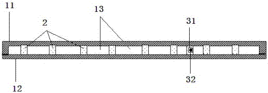
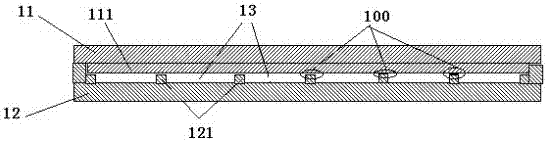
[0056] see Figure 2-4 , which is a structural schematic diagram of a vacuum glass in the embodiment. As shown in the figure: it includes two flat glass 11, 12 arranged in parallel, there is a gap for vacuuming between the two flat glass 11, 12; the edges of the two flat glass 11, 12 are sealed by high temperature melting. In Embodiment 1, the flat glass is preferably high borosilicate glass, and soda lime glass may also be selected. The inner surface of each plate glass 11, 12 has several supporting bars 111, 121 protruding from the inner surface of the plate glass; , 121 are staggered and stacked to form several support surfaces 100; a vacuum gap 13 is formed between the support bars 111, 121 on the inner surface of each plate glass, and the vacuum gap 13 between the two plate glasses communicates with each other. That is to say, the vacuum gap 13 between the support bars 111 of the upper plate glass 11 and the vacuum gap 13 between the support bars 121 of the lower plate ...

Embodiment 2

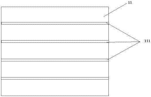
[0072] Its structure is basically similar to that of Embodiment 1, except that the support bars 111 and 121 are preferably arc-shaped with equidistant or unequal intervals.


PUM

PropertyMeasurementUnit
heightaaaaaaaaaa
widthaaaaaaaaaa

Abstract

The invention discloses vacuum glass and a processing method thereof. The vacuum glass comprises two pieces of plate glass arranged in parallel, wherein a gap for vacuumizing is formed between the two pieces of plate glass; the periphery of the two pieces of plate glass is sealed through high temperature melting; a plurality of supporting strips formed from bulges on the inner side face of the plate glass are arranged on the inner side face of each piece of the plate glass; the inner side faces of the two pieces of plate glass are overlapped by virtue of the supporting strips in a staggered manner; the supporting strips are overlapped in a staggered manner so as to form a plurality of supporting surfaces; a vacuumizing gap is formed among the supporting strips on the inner side faces of each piece of the plate glass; the vacuumizing gaps between the two pieces of plate glass are communicated with one another. The product disclosed by the invention has the effects of saving energy and insulating heat and sound and has the advantages of high vacuum degree, long service life and the like. Particularly, long-lasting vacuum aging is maintained in a manner of enlarging the vacuum chamber, and the product quality problem caused by different materials of the supporting part and the plate glass is solved.

Description

technical field [0001] The invention relates to the technical field of heat insulating glass and its manufacture, in particular to a vacuum glass and its processing method. Background technique [0002] Vacuum glass is to seal the surroundings of two pieces of flat glass, evacuate the gap and seal the exhaust hole. The gap between the two pieces of flat glass is 0.1-0.3mm. Generally, there is at least one of the two pieces of flat glass in vacuum glass. It is low-emissivity glass, which minimizes the heat loss through conduction, convection and radiation of vacuum glass. Its working principle is the same as that of glass thermos. Vacuum glass is the fruit of the combination of glass technology and material science, vacuum technology, physical measurement technology, industrial automation and building science, etc., a variety of disciplines, technologies, and processes. Its main technical effects are: energy saving, heat insulation and sound insulation. [0003] During the ...

Claims


Application Information

Patent Timeline
Patent Type & Authority Applications(China)
IPC IPC(8): C03B23/24
CPCC03B23/245
Inventor 朱盛菁朱津毅
Owner 朱盛菁
Why Eureka
Try Eureka