Vacuum coating system

A technology of vacuum coating and coating chamber, which is applied in vacuum evaporation coating, sputtering coating, ion implantation coating, etc. It can solve the problems of difficult installation, delay of process time, inconvenient maintenance, etc. The effect of high strength and convenient debugging

Pending Publication Date: 2022-07-08
布勒莱宝光学设备(北京)有限公司
View PDF0 Cites 0 Cited by
  • Summary
  • Abstract
  • Description
  • Claims
  • Application Information

AI Technical Summary

Problems solved by technology

[0005] 1. The processing requirements of the parts are high, the installation is difficult, and it is difficult to ensure that the process chamber, the manipulator chamber and the cage door are at the same horizontal position;
[0006] 2. It is inconvenient to maintain, and it is difficult to find the specific reason for the problem;
[0007] 3. The failure rate is high, the accuracy of picking and placing the hanging board is high, the overall strength is greatly affected by vacuum and temperature during use, and the probability of problems is high;
[0008] 4. The efficiency is low. After the process chamber fails, there is a high probability that it needs to break the vacuum to solve it, which delays the process time

Method used


Image

  • Vacuum coating system
  • Vacuum coating system
  • Vacuum coating system

Examples


Embodiment Construction

[0040] The technical solutions in the embodiments of the present application will be clearly and completely described below with reference to the accompanying drawings in the embodiments of the present application. Obviously, the described embodiments are only a part of the embodiments of the present application, rather than all the embodiments. Based on the embodiments in this application, all other embodiments obtained by those skilled in the art without creative work shall fall within the protection scope of this application.

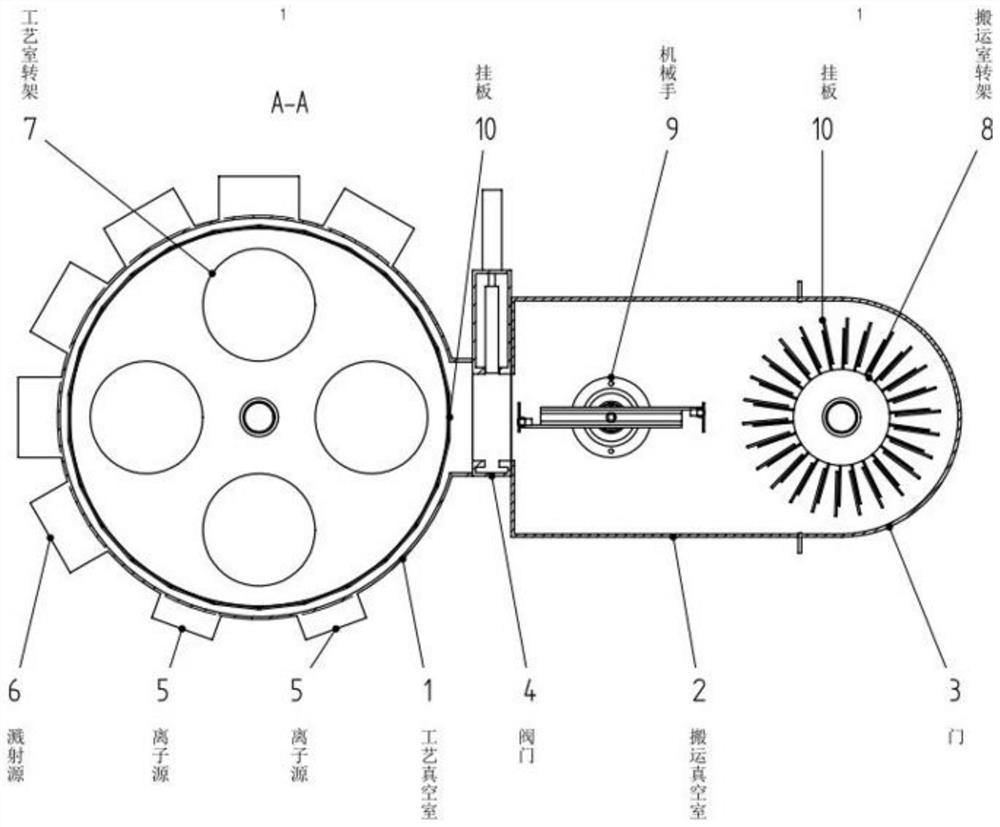
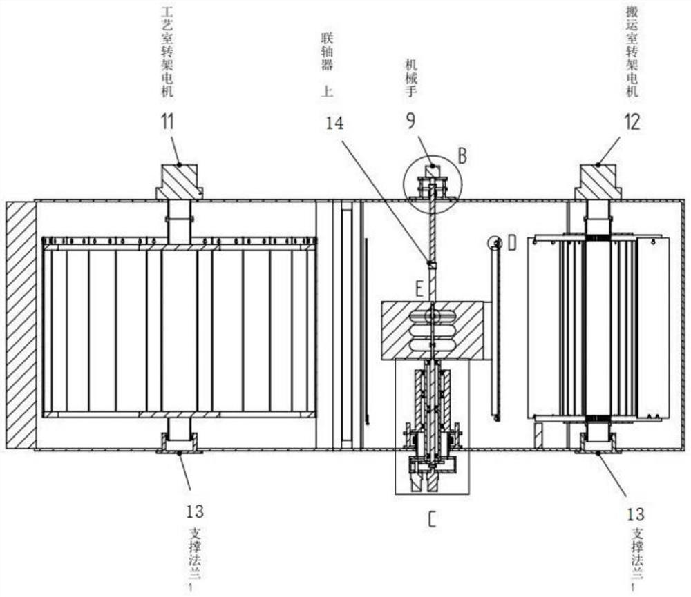
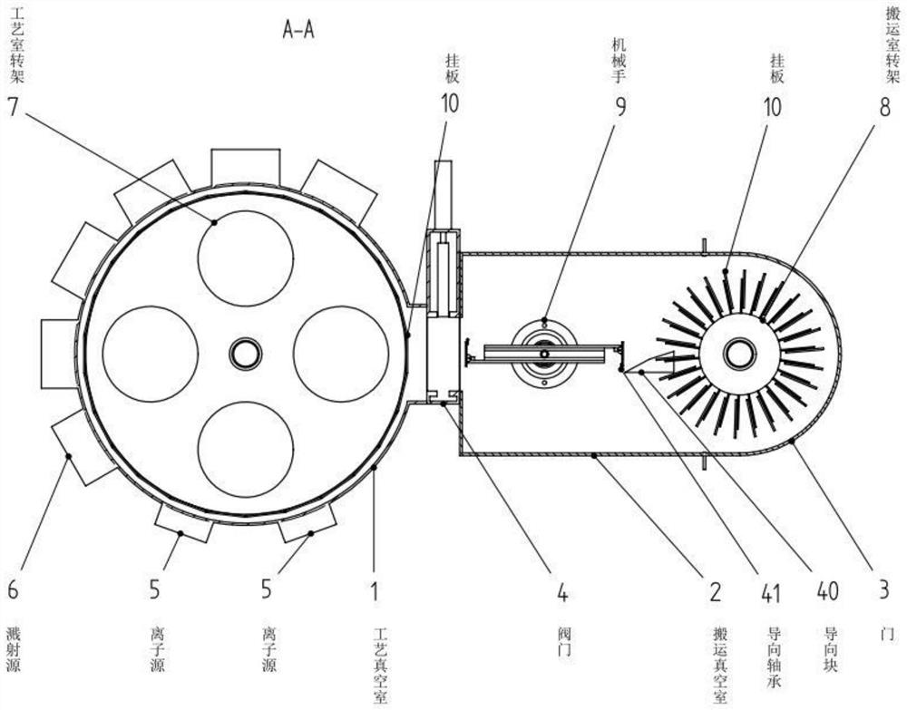
[0041] like Figures 7 to 18 As shown, an embodiment of the present invention provides a vacuum coating system, comprising: a coating device A, a transfer device B and at least one suspension operation device C which are connected in sequence.

[0042] In an exemplary embodiment of the present invention, two suspension operating devices C may be included. like Figure 7 to Figure 9 as well as Figure 17 and Figure 18 As shown, the suspension op...


PUM


Abstract

The invention provides a vacuum coating system which comprises a coating device, a transfer device and at least one suspension operation device which are sequentially connected, and the coating device is provided with a coating cavity, a rotary workpiece disc, a workpiece disc driving mechanism, an ion source, a workpiece disc supporting flange and an evaporation source; the suspension operation device comprises a suspension cavity, a cage frame arranged in the suspension cavity and a cage frame driving mechanism; the transfer device comprises a transfer cavity, a manipulator and a reversing guide rail; the transfer device is used for connecting the coating device and the suspension operation device; and during exchange operation, the coating device, the transfer device and the suspension operation device are all in a vacuum state. The device is convenient to mount and debug, low in failure rate, flexible in manipulator control and high in coating efficiency.

Description

technical field [0001] The application relates to the field of optical technology coating, in particular to a vacuum coating system. Background technique [0002] In the field of optical technology coating, improving the coating efficiency, reducing the failure rate of the coating system, and making the system maintenance more convenient has always been the goal pursued in the field of vacuum coating technology. [0003] Figure 1 to Figure 6 shows a current coating system such as Figure 1 to Figure 6 As shown, the coating system mainly includes a process chamber 1 and a transport chamber 2, which are separated by a valve 4 in the middle. [0004] Several ion sources 5 and sputtering sources 6 and other equipment are arranged around the process chamber 1, which are used to coat various film materials on the hanging plate 10 of the fixed substrate, and there are process chamber turrets 7 and hanging plates 10 inside the process chamber. , the turret 7 is driven by the top m...

Claims


Application Information

Patent Timeline
Patent Type & Authority Applications(China)
IPC IPC(8): C23C14/56C23C14/50C23C14/24
CPCC23C14/564C23C14/505C23C14/24
Inventor 魏国军张凯杰高福利李景薇李晓磊安永闫海涛
Owner 布勒莱宝光学设备(北京)有限公司
Why Eureka
Try Eureka