Device for welding a rail joint of a track

a technology for rail joints and devices, which is applied in auxilary welding devices, soldering apparatus, and ways. it can solve the problems of only being able to use welding units, the rails are shortened, and the longitudinal displacement has not been possible. it achieves great time savings and cost-effective effects

Active Publication Date: 2020-06-25
PLASSER & THEURER EXPORT VON BAHNBAUMASCHINEN GESELLSCHAFT MBH
View PDF0 Cites 1 Cited by
  • Summary
  • Abstract
  • Description
  • Claims
  • Application Information

AI Technical Summary

Benefits of technology

[0009]In an advantageous embodiment of the invention it is provided that the transverse displacement device comprises a hydraulic cylinder for applying a transverse displacement force. The hydraulic cylinder ensures a long useful life in working operations and precise accuracy of adjustment in order to align the two rail ends precisely with one another.
[0021]In particular, it is possible to exchange very short rail pieces. For example, a rail joint produced by thermite welding can be replaced in a simple manner in that a piece of rail a few meters in length is cut out. As replacement, a slightly longer rail piece (intermediate rail piece) is welded first to one cut end of the rail, wherein it overlaps the other cut end of the rail. When welding the second rail piece end, the overlapping is used, according to the invention, for compensating the material consumption.

Problems solved by technology

However, this results in a slight shortening of the rails which has to be compensated.
Currently, welding units can only be used in places where the rail material consumption is compensated by a longitudinal displacement of the rail.
When removing an old rail joint and inserting an intermediate rail piece, a longitudinal displacement has heretofore not been possible.

Method used


Image

  • Device for welding a rail joint of a track
  • Device for welding a rail joint of a track
  • Device for welding a rail joint of a track

Examples


Embodiment Construction

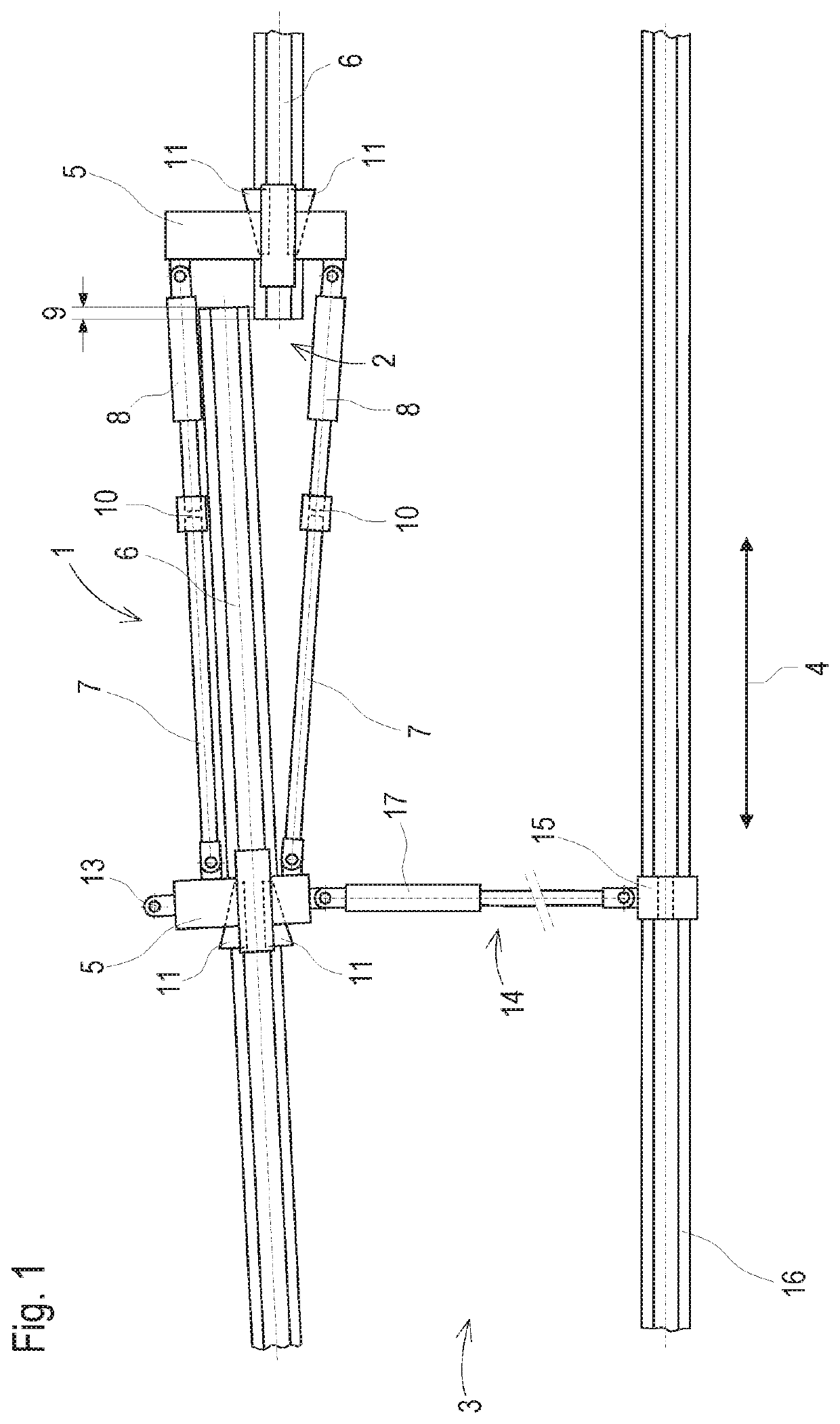
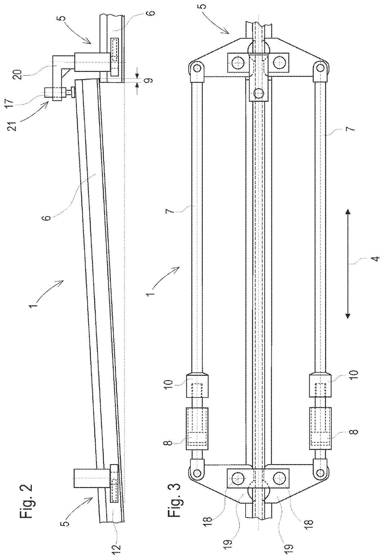
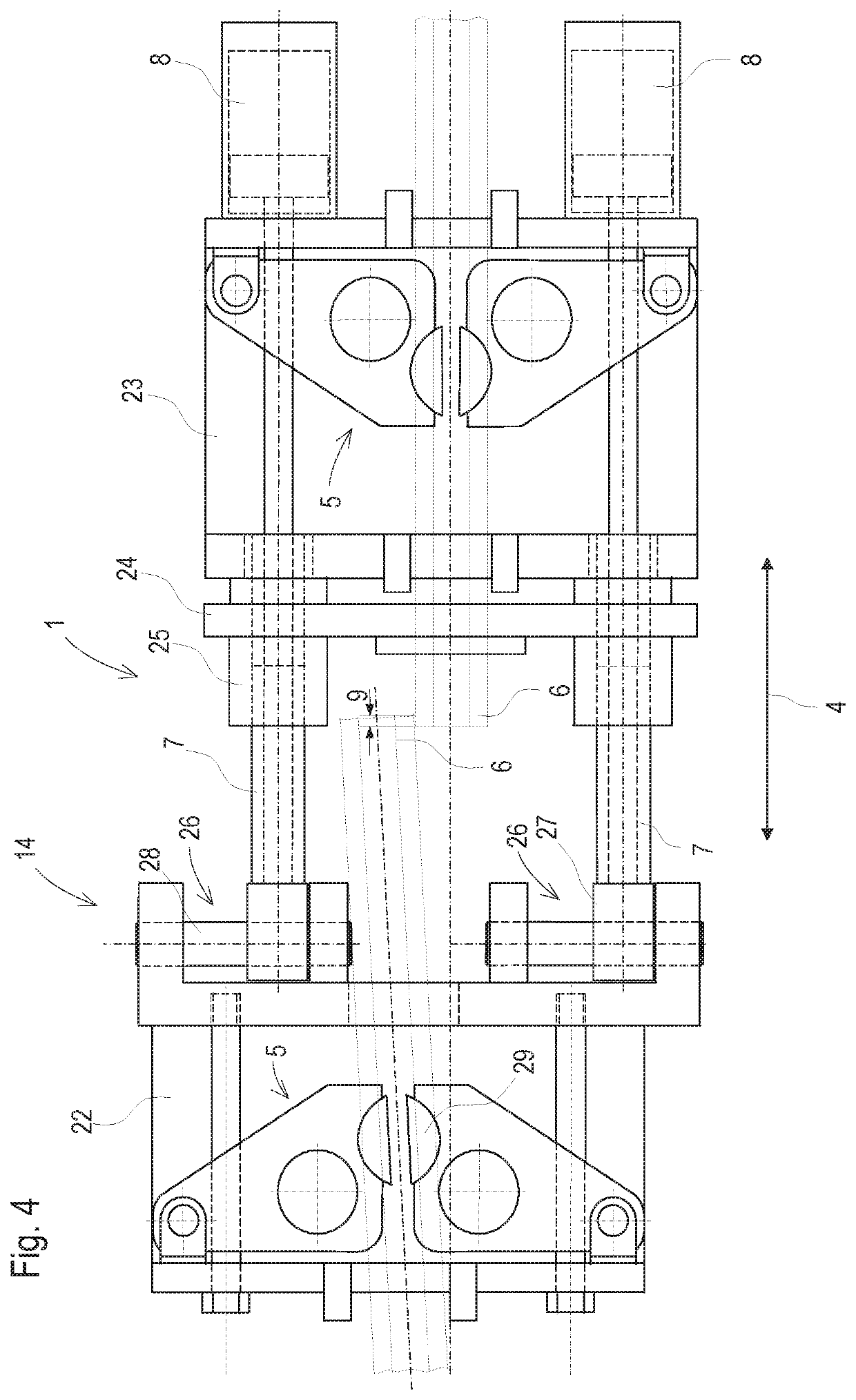
[0033]FIG. 1 shows a top view of a device 1 for welding a rail joint 2 of an installed track 3, comprising two rail clamping devices 5 spaced from one another in a rail longitudinal direction 4 which are connected to one another via two push rods 7 and each are gripping one rail end 6. Associated with each push rod 7 is a first hydraulic cylinder 8 to press the two rail ends 6 apart from one another so far that no more overlapping 9 exists. Each push rod 7 has a turnbuckle sleeve 10 to precisely align the two rail clamping devices 5 with one another.

[0034]The respective rail clamping device 5 is simply pushed from above onto the associated rail end 6 and secured against displacement in a rail longitudinal direction 4 with wedges 11 which engage a rail web 12 in each case. The rail clamping device 5 arranged on the rail end 6 to be displaced has a fastening lug 13 at each side for attaching a transverse displacement device 14. The transverse displacement device 14 comprises a support...


PUM

PropertyMeasurementUnit
transverse displacement forceaaaaaaaaaa
transverse displacementaaaaaaaaaa
temperatureaaaaaaaaaa

Abstract

A device for welding a rail joint of a track, comprising two rail clamping devices spaced from one another in a rail longitudinal direction which are connected to one another via push rods to press rail ends apart prior to welding. In this, it is provided that at least one rail clamping device is coupled to a transverse displacement device for flush-aligning the rail ends after being pressed apart.

Description

FIELD OF TECHNOLOGY[0001]The invention relates to a device for welding a rail joint of a track, comprising two rail clamping devices spaced from one another in a rail longitudinal direction which are connected to one another via push rods to press rail ends apart prior to welding. The invention further relates to a method for welding a rail joint by means of such a device.PRIOR ART[0002]Mobile welding units are increasingly used for welding together two rails of a track. In this, differing from the older thermite welding, the rail ends are fused without the addition of foreign materials. However, this results in a slight shortening of the rails which has to be compensated.[0003]As a rule, at first several rail sections are welded with the rail fastenings being loosened. Then, in the course of a closure welding, the rail line receives its longitudinal tension prescribed for the prevailing ambient temperature. At temperatures below the mean annual temperature (neutral temperature), a ...

Claims


Application Information

Patent Timeline
Patent Type & Authority Applications(United States)
IPC IPC(8): E01B29/46B23K37/04B23K11/04E01B29/44
CPCE01B29/44B23K37/0435E01B29/46B23K11/046B23K11/04B23K2101/26B23K37/0426
Inventor MUEHLLEITNER, HEINZ
Owner PLASSER & THEURER EXPORT VON BAHNBAUMASCHINEN GESELLSCHAFT MBH
Why Eureka
Try Eureka