Resistor having low temperature coefficient of resistance

a resistor and coefficient technology, applied in resistor details, base element modifications, instruments, etc., can solve the problems of significant deviation in monitoring the current passing through the device, inaccurate sensing voltage readings at the sensing terminal, etc., to achieve low temperature coefficient of resistance, reduce sensing voltage deviation of current, and low resistance coefficient

Active Publication Date: 2020-06-25
CYNTEC
View PDF0 Cites 5 Cited by
  • Summary
  • Abstract
  • Description
  • Claims
  • Application Information

AI Technical Summary

Benefits of technology

[0004]The present disclosure provides a resistor having low temperature coefficient of resistance, using an obstructing structure for reducing the sensing voltage deviation of a current passing through the resistor.
[0005]A resistor having low temperature coefficient of resistance of an embodiment according to the invention includes a resistive part, a first conductive part, and a second conductive part. The resistor thereon defines a main current direction. The first conductive part is connected to a side of the resistive part in the main current direction. The first conductive part has a first sensing portion and a through slot. The first sensing portion is located between the first through slot and the resistive part. The through slot includes a first slot section and a second slot section which are located at two opposite sides of the first sensing portion relative to the main current direction and connected with each other. The first slot section extends from a first start point along a first path toward the resistive part and ends with a closed end. The second slot section extends from the first start point along a second path toward the resistive part and ends with a closed end. The first path has a first parallel component, parallel to the main current direction, and a first perpendicular component, perpendicular to the main current direction. The second path has a second parallel component, parallel to the main current direction, and a second perpendicular component, perpendicular to the main current direction. The second conductive part is connected to another side of the resistive part in the main current direction. The second conductive part has a second sensing portion. Thereby, the through slot can obstruct a current passing through the resistor so as to effectively reduce the sensing voltage deviation of the current through the first sensing portion and the second sensing portion.
[0006]A resistor having low temperature coefficient of resistance of another embodiment according to the invention includes a resistive part, a first conductive part, and a second conductive part. The resistor thereon defines a main current direction. The first conductive part is connected to a side of the resistive part in the main current direction. The first conductive part has a first protrusion block extending outward perpendicular to the main current direction and ending with an end perpendicular to the main current direction. The first conductive part has a first sensing portion at the first protrusion block. The second conductive part is connected to another side of the resistive part in the main current direction. The second conductive part has a second sensing portion. The first sensing portion and the second sensing portion are disposed at two sides of the resistive part respectively. Thereby, the first protrusion block forms an obstructing structure for reducing the sensing voltage deviation of a current passing through the resistor through the first sensing portion and the second sensing portion.

Problems solved by technology

However, most devices have a non-zero TCR that can lead to inaccurate sensing voltage readings at the sensing terminals particularly when the temperature of the device varies.
Copper has a TCR of 3900 ppm / ° C. while the resistive material is typically less than 100 ppm / ° C., which makes the sensing terminals show a higher TCR than desired, resulting in significant deviation in monitoring the current passing through the device.

Method used


Image

  • Resistor having low temperature coefficient of resistance
  • Resistor having low temperature coefficient of resistance
  • Resistor having low temperature coefficient of resistance

Examples


Embodiment Construction

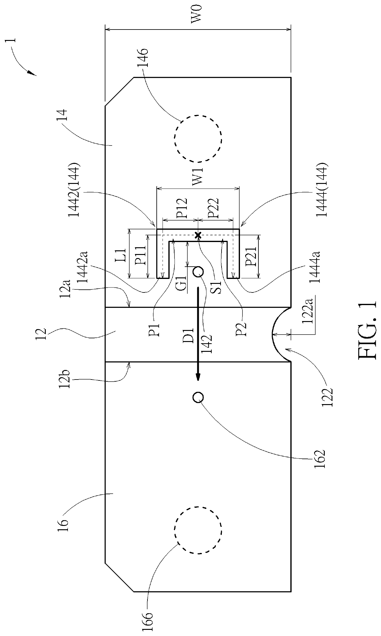
[0020]Please refer to FIG. 1. A resistor 1 having low temperature coefficient of resistance according to an embodiment includes a resistive part 12, a first conductive part 14, and a second conductive part 16. The resistor 1 thereon defines a main current direction D1 (indicated by an arrow in FIG. 1). The first conductive part 14 is connected to a side 12a of the resistive part 12 in the main current direction D1. The first conductive part 14 has a first sensing portion 142 (indicated by a circle in FIG. 1), a first through slot 144, and a first connecting portion 146 (indicated by a dashed circle in FIG. 1). The first sensing portion 142 is located between the first through slot 144 and the resistive part 12. The first through slot 144 is located between the first connecting portion 146 and the first sensing portion 142 along the main current direction D1. The second conductive part 16 is connected to another side 12b of the resistive part 12 opposite to the first conductive part ...


PUM

PropertyMeasurementUnit
central angleaaaaaaaaaa
temperature coefficient of resistanceaaaaaaaaaa

Abstract

A resistor having low temperature coefficient of resistance includes a resistive part and two conductive parts connected to opposite sides of the resistive part. One conductive part has a through slot and a sensing portion between the through slot and the resistive part. The through slot has two inter-connected sections. Each section extends and ends with a closed end and has a parallel component, parallel to a main current direction defined on the resistor, and a perpendicular component, perpendicular to the main current direction. Another resistor having low temperature coefficient of resistance includes a resistive part and two conductive parts connected to two sides of the resistive part respectively. Each conductive part has a protrusion block, extending outward perpendicular to a main current direction defined on the resistor, and a sensing portion at the protrusion block.

Description

CROSS REFERENCE TO RELATED APPLICATIONS[0001]This application claims the benefit of U.S. Provisional Application No. 62 / 783,208 filed on Dec. 21, 2018 which is incorporated herein by reference.BACKGROUND OF THE INVENTION1. Field of the Invention[0002]The present invention relates to a four terminal current sense resistor of low temperature coefficient of resistance.2. Description of the Related Art[0003]Current sense resistors have been available for the electronic market for many years. Their construction typically includes a flat strip of a resistive material that is coupled between high conductivity metal terminals forming the main terminals of the resistor. A pair of sensing terminals can be formed in the main terminals thereby creating a four terminal device. The main terminals carry the majority of the current through the resistor. The sensing terminals produce a sensing voltage that is proportional to the current passing through the resistor. Such resistors provide a mechanis...

Claims


Application Information

Patent Timeline
Patent Type & Authority Applications(United States)
IPC IPC(8): G01R1/20G01R19/00H01C1/14H01C7/06
CPCG01R1/203H01C7/06H01C1/14G01R19/0092H01C3/00G01R15/18H01C1/148
Inventor HUNG, TZU-HAOLUO, YING-DA
Owner CYNTEC
Why Eureka
Try Eureka