Wireless power transfer method and device therefor

a wireless power transfer and wire technology, applied in the direction of electric power, transportation and packaging, electric vehicles, etc., can solve the problems of difficult organization, large working space of cables, and poor appearan

Active Publication Date: 2020-06-25
LG INNOTEK CO LTD
View PDF0 Cites 7 Cited by
  • Summary
  • Abstract
  • Description
  • Claims
  • Application Information

AI Technical Summary

Problems solved by technology

Therefore, many cables occupy considerable working space, are difficult to organize, and are not good in appearance when a lot of devices employing the terminal supply method are used.
In addition, the terminal supply method may cause problems such as instantaneous discharge phenomenon due to different potential difference between terminals, burnout and fire caused by foreign substances, natural discharge, or deterioration of battery life and performance.
In addition, when the foreign substance includes an electronic device or the like, noise may be caused when the electromagnetic field is absorbed.
In general, the noise of about 40 dB is enough to make people feel uncomfortable to sleep, and the noise occurring when the electromagnetic field is absorbed is about 35 dB to 40 dB, which may cause inconvenience to a person.
In addition, when the wireless power transmitter generates a detection signal to detect a wireless power receiver, a current flowing through coils increases to generate heat and consume unnecessary power.
In addition, there is a problem that the electromagnetic field generated by the wireless power transmitter interferes with an FM radio frequency.

Method used


Image

  • Wireless power transfer method and device therefor
  • Wireless power transfer method and device therefor
  • Wireless power transfer method and device therefor

Examples


Embodiment Construction

[0059]Hereinafter, embodiments of the present disclosure will be described in detail with reference to the accompanying drawings. However, it should be understood that the technical scope of the present disclosure is not limited to some embodiments described, but may be implemented in various forms, and one or more of the components may be selectively selected, combined or substituted within the technical scope of the present disclosure. Unless defined otherwise, all the terms (including technical and scientific terms) used herein have the same meaning as commonly understood by one of ordinary skill in the art to which the present invention belongs. It will be further understood that the terms, such as those defined in commonly used dictionaries, should be interpreted as having meanings that are consistent with their meanings in the context of the relevant art. The terminology used in embodiments of the present disclosure is for the purpose of describing particular embodiments only ...


PUM


Abstract

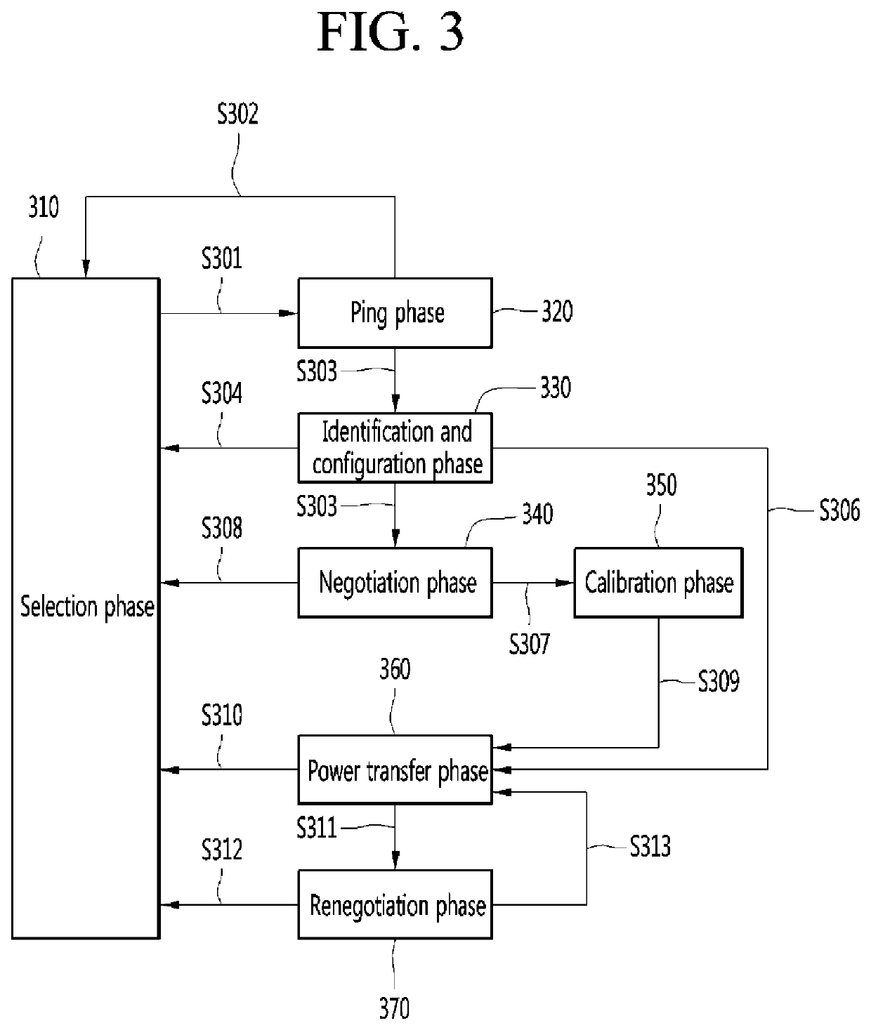
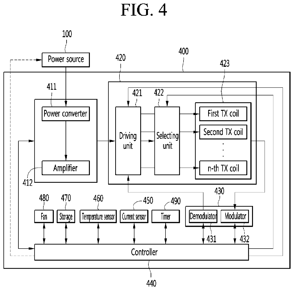
The present invention relates to wireless power transmission technology, and more particularly, to a wireless power transfer method and a device therefor. The wireless power transfer method may include operating with a first driving voltage, determining whether a ping phase is entered, determining whether the wireless power transmitter is in a first state when the ping phase is entered; and operating with a second driving voltage when the first state is determined.

Description

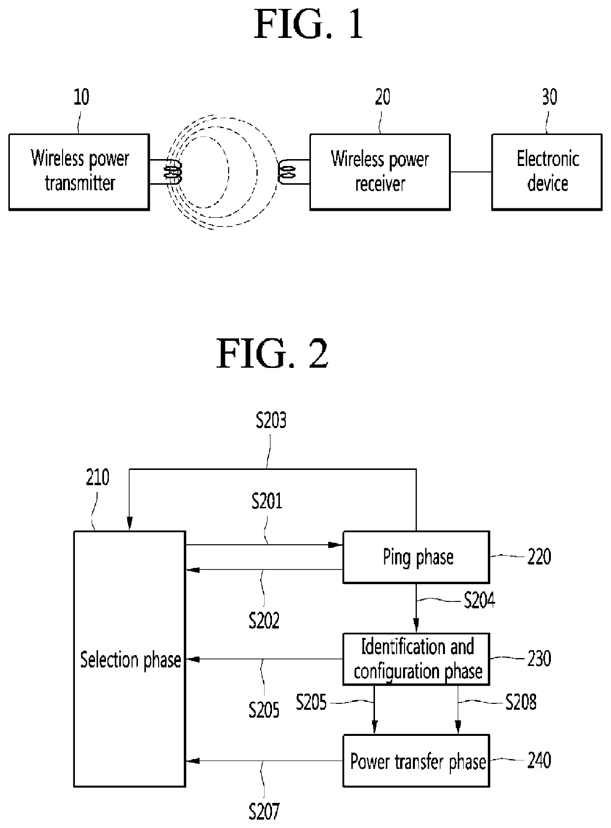
TECHNICAL FIELD[0001]The present invention relates to wireless power transfer technology, and more particularly, to a wireless power transfer method and a device therefor.BACKGROUND ART[0002]Portable terminals such as mobile phones and laptop computers include a battery that stores power and circuits for charging and discharging the battery. In order for the battery of the terminal to be charged, power is to be supplied from an external charger.[0003]In general, as an example of an electrical connection method between a charging device and for charging a battery with power and the battery, there is a terminal supply method of supplying electric energy to the battery through a terminal of the battery by receiving commercial power and converting the commercial power into a voltage and a current corresponding to the battery. This terminal supply method is accompanied by the use of a physical cable or wire. Therefore, many cables occupy considerable working space, are difficult to organ...

Claims


Application Information

Patent Timeline
Patent Type & Authority Applications(United States)
IPC IPC(8): H02J50/80H02J50/60H02J50/12H02J7/02
CPCH02J7/02H02J50/60H02J50/12H02J50/80H02J50/402H02J50/20H02J7/00714
Inventor PARK, JAYLEE, JONG HEON
Owner LG INNOTEK CO LTD
Why Eureka
Try Eureka